
robdyck
-
Posts
4977 -
Joined
-
Last visited
Content Type
Profiles
Forums
Gallery
Everything posted by robdyck
-

Canada Specific Chief Architect Template Plan & Workflow
robdyck posted a topic in Offering Services
Hi everyone, I hope you’re all having a busy and productive week! I’m looking to get some friendly feedback from the Canadian users in the community regarding our daily workflows. Chief Architect is an incredibly powerful tool right out of the box, but as Canadian designers and builders, we all know it takes a fair amount of setup to fully align it with our local building codes, regional drafting standards, and client presentation expectations. Over the years, I’ve poured a lot of time into optimizing a master template plan designed specifically to streamline a Canadian workflow. The goal wasn't to change how Chief works, but to leverage its core strengths so everything feels intuitive, fast, and completely straightforward from day one. I’ve focused heavily on elevating the default graphic interfaces to deliver a highly polished, presentation-ready look out of the box, including: Refined Graphic Standards: Tailored text styles, clear dimension defaults, and organized layer sets that instantly look crisp and professional on local construction sets. Enhanced 3D & Rendering Defaults: Dialed-in environmental and camera settings so you can jump straight into high-quality client presentations without extra setup time. Streamlined Project Defaults: Cleaned-up defaults for a predictable, efficient out-of-the-box building experience that lets you focus on design rather than tweaking settings. I’m considering packaging and offering this template plan for sale to help other Canadian professionals save dozens of hours of backend configuration and get straight to creating. Before I finalize everything, I’d love to know your thoughts: Would a localized, pre-configured Canadian template add value to your current business workflow? What regional details do you find yourself spending the most time setting up when starting a new project? I really value the expertise in this forum and would love to hear if this is something you’d find helpful. Thanks so much for your time and insights! -
SHOWERS.calibz
-
I've done something slightly different. I've separated the various components so that I have a choice of shower doors and faucets and I place them as an architectural block. You can go a bit further and add a tile trim around the shower, useful if you'll be showing interior views. By doing this, you can easily adjust the shower and have the label auto-update the size by using the width and depth macro. And, by adjusting the bounding box to negative 0.5 on the left, right and back, it becomes simpler to place the shower against the framing. Rather than change shower sizes in the plan, I've done this in advance and have what I need in my library. I find it faster to find and replace a symbol than adjust the one in place. Now, I know that wasn't macro help, but hopefully it's still useful.
-
I took a stab at it as well. A library symbol is attached, all you need to do is create an arched door way and place this symbol in your plan. For anyone wondering...NOT made with cabinet tools! PANELED ARCH.calibz
-
Good question Jason. For my own plans, I don't label the assembly calculations on those details. Instead, I use an assembly schedule (with all the effective thermal resistance calculations) and I 'tag' the various assemblies in section views.
-
I wouldn't hold my breath for that kind of feature and even if they did provide it, I wouldn't expect the flexibility needed or the control of appearance. I've been using 3d details for about 15 years with full control of what I model. I use Chief's tools to my advantage and I don't need to fight any settings to accomplish what I want. Because of that, creating new details and adjusting existing details is very quick and very stable. I have no reason to think that Chief will develop a 3d detail tool that automates the inclusion of components of flashing, tape, membranes, rebar, bolts, and other structural hardware. Because I have created so many of them, I know what goes into making them look right and knowing the level of difficulty involved, I have absolutely no expectation of Chief developing any sort of tool that replaces what I currently do.
-
I have often wished for this capability but it does not exist. All newly created section or elevation views will inherit the drawing sheet that is active in plan view. So, let's say you want to create all your interior wall elevations at 1/2" scale and you'd like the drawing sheet set properly. In plan view, change the drawing sheet size and scale to suit your preferred elevation views. Create all your interior elevation views. Now, you can change the plan view drawing sheet back to what is intended for the majority of your plan views. For all existing elevation or section views, the drawing sheet must be changed manually as needed. This is a bit of a nuisance if you frequently use multiple sheet sizes like I do. My default is Arch D sheets (36"x24") but I have several customers that require Tabloid (17"x11") so I often need to change the drawing sheet for all the existing elevation cameras, one at a time. It's an annoying waste of time.
-
For these types of views, you will need to pick your poison. Chief has all the tools...you can create molding polylines from a cabinet, and you can make custom countertops. BUT, that overrides a lot of function / feature just for line weight control. My own suggestion would be to find a balance of line weight display that works for you but doesn't 'fight' Chief...which sooner or later becomes a losing battle. I'm familiar with the sample you referenced but...and this is a big but...that's a different software AND definitely a different pay scale! Chief can do a great job of telling the story while working within it's natural boundaries.
-
https://3d-viewer.chiefarchitect.com/go?share=023704475132725
-
Not new! It's tricky to remember to go looking for those new features to implement into an existing template.
-
Yes, this can be done by using several preset Room Schedules that include / exclude your rooms based on the room type. One of the starting points to this is a very thorough predefined list of rooms as well as a disciplined method of adding new rooms when needed. The next step is customizing each schedule based on the included rooms. It can also help to learn some of the more creative methods of schedule manipulation...outside of the box thinking that Chief doesn't address in the help file.
-
@Steve_Nyhof Could probably chime in on creatively using schedules to sort out various area totals! I think a good summary is this: Nothing is entirely automatic...unless you setup perfect systems and then never deviate from those systems. In my opinion and in my own practice, perfection has been difficult to achieve because there are so many variables that go into a project. Customer preferences, land use bylaws, building codes, regional methods can all vary significantly. I just had a project where I tested some of the more creative ways to use the Room Schedule tools to total various areas. I could achieve accurate totals as long as I included at least 1 or 2 decimal places, needed to circumvent the totaling error from adding up multiple rounded values. I was not willing to include decimals in my area tables, nor was I willing to report inaccurate information, even if it is only slightly inaccurate. And while I would love a RONCO quality schedule for area reporting (set it and....FORGET IT!!!), I have instead opted to make the polyline method part of my work flow to ensure accuracy. Using colored polylines, adjusted near the end of the project, also provides you with a very simple visual cue to what is being reported and where it is positioned. Contrast that to hunting through the list of included room items in a schedule, in a tiny dialog box that can't be expanded, is (for me) a great way to ensure an error or omission. It's also worth noting that the polyline method combined with Custom Schedules and Custom Object Fields can eliminate the need for macro writing or out-sourcing macros. In short, as your system progresses in complexity, the likelihood of user error will increase.
-
As long as you have very controlled room uses, you can create a myriad of simple schedules that simply include or exclude certain rooms. If you rename rooms, or need to shift a room from one category to another, this can be prone to user error, so you would need a crystal clear room naming convention that you adhere to with a cult-like devotion. I still use polylines...I have a few other uses for them anyway so I don't mind.
-
So...we just need Chief to consult with people who know how homes are built! Obviously the problem with manually providing the heel height info the way I have been is more prone to typo's or forgetting updates. I've made errors at least twice since I started including the heel height (which I did as soon as you could use schedules for roofs). Luckily, the truss guys know to call and ask if there's an issue...and they still thank me for giving them this info because no one else does!
-
It's important to note that the heel height does not always report correctly in the roof dialog. It seems to be an internal calculation of the baseline height minus the top plate height, but there are times when chief reports the top plate height incorrectly in the roof dialog and then the heel height also reports incorrectly. This is even when all rooms are exact and according to defaults, and even when all baselines are in the exact correct position. The baseline elevation is an exact and absolute elevation whereas the heel height is relative and not always exact. Chief would absolutely have to do some work to ensure more accurate reporting of the heel height and the top plate height before allowing use of these values. I always include the heel height value in a roof schedule by just using a Custom Field, and you have to be careful not to just regurgitate what Chief's roof dialog is showing. Obviously the likelihood of these values reporting incorrectly increases with the complexity of the roof.
-
As far as I know, using a convert pdf to jpg tool is still the simplest way.
-
I only suggest turning the marker on for inspection purposes. Another useful inspection tool for this is dimensioning in section view. You will notice that Chief will create a point marker when you try to dimension to the top of a railing cut by the section. This sort of tells us that we can't really locate rails with the dimension tool (at least that's my conclusion). Summary: If I needed to move the dimension away from the railing, I would also simply add a point marker or cad line and dimension to that (exactly what you alluded to).
-
A simple clue as to what Chief is locating can be found by going to the Extensions / Markers tab and checking 'Draw Marker'. You'll see that Chief is locating the top of plate. Because it's an auto-locate, it jumps to a different top of plate locate when the dimension is moved. The 'Why' I can't answer...just the 'what'. You should also notice that once that dimension is moved away from the wall, it is probably next to impossible (if not entirely) to locate the top of the railing. A point marker is needed.
-
For the roof, single-click on one plane's bottom edge, press '2', then single-click on the opposing plane's bottom edge. That will join them to form a level valley which you can take care of however you see fit.
-
20260528-2049-32.6272496.mp4
-
One of the cleanest ways I can quickly come up with is to add wall coverings to rooms. Of course, the wall covering height and elevation needs to be specified manually. Follow this by editing the component for the wall covering (I chose ID: General and Accounting Code: 5300 - Painting Interior). Then, create a materials list polyline on a per room room basis or apply the wall covering to as many rooms as needed. Keep in mind that Rooms don't report to the materials list, so if multiple rooms are included in the mat. list, you can't really identify the source of each paint material, unless you can figure out a macro to place in one of the available component fields that will report the name (I haven't figured that out). Of course, you can manually enter the room name in one of the available fields. But, this will allow you to create a material list for that category only by choosing which columns to include.
-
Your best bet is to look through the Armstrong Flooring catalog. If you don't have it, you can download by following the link below. https://www.chiefarchitect.com/3d-library/index.php?r=site/detail/709
-
Try making the same drawer using framing members. Just model it 'flat' in plan view (this will give you the mitering option). Then convert to symbol and rotate as needed. It might also be a material mapping issue after the symbol is created. Can you post an empty plan with the 3d solids as well as the completed drawer front?
-
All you need to do is select a molding profile for the interior sill from the library. That will provide a separate field for the Interior Sill Molding in the Materials Tab. Unfortunately, this profile needs to be the correct size in the library and even then, it will build to the bottom of the window frame. AFAIK, There is no setting to adjust the reveal of a window sill.
-
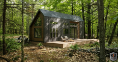
From the album: Tiny Homes

