

Chopsaw
-
Posts
7505 -
Joined
-
Last visited
Content Type
Profiles
Forums
Gallery
Posts posted by Chopsaw
-
-
That would certainly be a nice feature to have but I don't think that there is any way to get there as the software is now.
You would need to transfer your site plan to a metric template and reference it on your layout, or if there are not many elevation lines as pictured I would just do the conversions and paste a text box over top but you may end up with some funky decimal places converting feet to meters.
-
 1
1
-
-
22 minutes ago, creatrix said:
And I haven't figured out how to make a copy of the plan in order to input a smaller sized file.
File > Save As > and give it a new name then edit that copy and take out fixtures and furnishings that are not needed.
You might also need to post the PDF if you were unable to create a material from it.
You can have a look in Alan's plan file unless he posted it as X14.
-
3 hours ago, creatrix said:
And why is it cut off in my camera view?
That seems like it is most likely a result of drawing the p-solid in elevation view when the elevation camera is not square to the wall so either the wall is not straight or the camera slipped when placing it so check the wall angle and you can't adjust an elevation camera so if it of out of wack you will need to replace it and make sure angle snaps are on when you do it and it will be much easier.
-
3 minutes ago, creatrix said:
My zip is too large. How do I get it smaller?
Sorry they reduced the limit. You either have to delete some unnecessary stuff from a copy of your plan file or upload the file to your cloud account and post the link to the file here.
-
12 minutes ago, creatrix said:
I've made a mess. I'm just going to ask support because I've got so many issues and have no idea why — not feeling LOL but what else to do?!
You can always post your plan file here when tech support is closed.
-
Your p-solid must be skewed somehow. Check it in plan view or recreate in elevation view and place in front of hanger board.
-
You could use the Screen Capture tool to create a material from the Imported PDF then apply to the wall or a p-solid. Enlarge it on your screen though so you capture as many pixels as possible to increase the resolution.
-
7 minutes ago, HumbleChief said:
It's also important to remember that most technical issues start with a post to the forum to check the validity of any misbehavior before reporting to tech staff.
Very true and possibly an indication that there is another problem lurking that causes it to be true.
-
 1
1
-
-
29 minutes ago, glennw said:
You need to move your top Custom Plasterboard wall layer up to separate it from the main layer.
That would do it. Good eye. Thanks Glenn.
-
13 minutes ago, AdeleMinton said:
in the default settings - Walls - interior walls - wall types - change colour. I actually duplicated the drywall in library, renamed to plasterboard as we refer to it and used a paint colour.
Ok great you avoided the most common mistake of adding a thin extra layer to you wall definition that seems quite logical but does not work.
I am also not sure what the issue might be but the plan file may show what the problem is.
-
I see you are not using the default wall colour. How did you change that ?
-
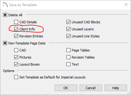
Also are you using the "Save as Template" options to update your templates ?
-
3 minutes ago, Kbird1 said:
These Files are from a Home Designer Program not Chief ...... UNLESS you named them that?
They used to be named that in Premier and could have been migrated. Just another example of background programming that is assumed to be helpful but no way to control if it is not.
-
Pretty difficult to get a good seamless totally random material. When it maters I have done individual stones with p-solids for an authentic look.
Then you have more control over the material application as well.
-
8 minutes ago, glennw said:
I am pretty sure that copying existing framing members that make up the truss works OK.
Yes I believe that is the only way. Also if I remember correctly a cad line would only work for a square cut but now it seems to be ok for any straight cut.
-
33 minutes ago, glennw said:
These members are General framing members, so if you need a new member you can use a General Framing member.
Not the same kind of "General Framing Member" that you can draw with the General Framing tool though unless you have a special trick ?
-
True it is not all there but there are more available at the 3D Warehouse and I believe all can be downloaded from Simpson.
So perhaps this belongs in suggestions so we can get an update to the chief library catalogue ?
-
So something more like this ?

-
Plenty of ways to do that. You could put a transparent gray over your cross hatch but likely better and sharper to put a cross hatch without background over top of a solid gray.

-
I have another program that may be able to convert the .fbx files to .dae
Willing to give it a try if you like.
-
Hi Mike, Just go ahead and make a copy then open up the DBX and change the radius by the amount of your desired offset.
-
First scale the imported plan. Then trace over with cad lines and turn on the Length and Angle settings. Those format options are General Cad Defaults. Let us know if you run into any other issues.
-
4 minutes ago, KnotSquare said:
Ooh, Ooh! Closer yet. Do you know how to control the first number?
It may be possible but raises the complexity significantly. The " # " is rather special by itself and not sure it can be altered.
Set it up with A1.0 as a fixed number and then the next sheet can be A1.# for now and see how that goes.
-
1
-
-
Not quite. I use the %page% macro just in fine print for my own collating purposes but it just gives the simple sequence 0,1,2,3,4......


Will this computer configuration work well with X14?
in General Q & A
Posted
I would say you have a good base setup but if you are going to be doing any significant amount of RTRT then you should have a 3070Ti or better.
Also the ability to add more RAM if you run other software with chief or have multiple monitors. Minimum of 1TB SSD unless you want to do a lot of file transfers with a HDD. I started with a 256 GB SSD and had it filled in a mater of months.