








DefinedDesign
-
Posts
256 -
Joined
Content Type
Profiles
Forums
Gallery
Posts posted by DefinedDesign
-
-
Just found out this feature will be in x18!
-
 1
1
-
-
Wondering how NotebookLM would handle this. I've tried in ChatGPT and the results are miserable.
-
1
-
-
On 6/18/2026 at 3:07 PM, DBCooper said:
If you want to turn off the auto fillers for just one cabinet, hold down the shift-key when you select it and make it into an architectural block. This will not let the cabinet attach to any other cabinets or walls outside of the block.
Thanks DB, question when it converts to an architectural block will it still populate in the materials lists for the cabinet schedule and countertop quantities?
-
1
-
-
32 minutes ago, JKEdmo said:
turn off auto cabinet fillers in cabinet defaults
Thanks Jim! This is problematic as I have cabinets in others rooms that need the automatic filler. Is there a way to turn it off on just the cabinet?
-
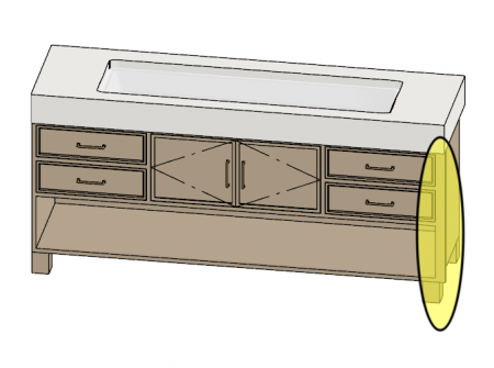
Have a custom vanity/base cabinet that is intentionally located 1” away from the wall on the right side.
The cabinet box is positioned correctly, but Chief is automatically extending the right end of the cabinet/countertop assembly to close the gap and reach the wall (highlighted in yellow in the image below).
- Right End Extension is set to 0
- The cabinet is intentionally offset from the wall
- I want the cabinet and countertop to stop at the cabinet end and maintain the 1” gap
- I do not want the cabinet or countertop to auto-fill the space to the wall
-
On 5/29/2026 at 1:42 PM, Renerabbitt said:
Renee, thank you for the video. After watching it I can appreciate each object in Chief much more than I have in the past. I had no idea the level of complexity it takes to generate a material. What do you charge to generate materials?
-
On 5/28/2026 at 5:50 PM, Renerabbitt said:
This just needs normal map
Thanks, I’ll do some homework in the Chief reference manual on what this is, appreciate the help for a starting point.
-
On 5/29/2026 at 1:35 PM, JonathanK said:
Added the texture to library and attached it here for your pleasure...
Thank you. I appreciate the file. I will most certainly use. It. I am very unfamiliar with the process you wrote about. I will search Chief’s video training to see if I can teach myself how to do this.
-
On 5/26/2026 at 8:52 AM, GeneDavis said:
AI is the best way to go
Thank you for taking the time to share the video. I actually follow that YouTube channel and have tried many of the suggestions using ChatGPT, NanoBanana, and Gemini, but unfortunately my results have not been very successful. It may be that he is starting from SketchUp instead of Chief Architect, which could allow the AI tools to perform better in his workflow.
For me, I have found that the amount of time spent trying to get AI to generate accurate visuals that truly help the client understand the final result has not been worthwhile. As a small builder, we also have to be careful financially and cannot justify adding multiple expensive software tools and subscriptions.
I truly appreciate you taking the time to respond. I was hoping there might be a solution within Chief Architect itself that could produce the type of results we are looking for.
-
19 minutes ago, para-CAD said:
Does it print?
It does not print. Thank you. -
Chief Architect X17 Project Management Question:
When opening a new layout page, there is a small crosshair/reference marker appearing on every single layout page, including completely new blank layout files.
It is:
- not selectable
- does not seem tied to Page 0
- appears in the exact same location on every layout page
- survives reopening the file
- appears even in a brand new test layout
I initially thought it was:- a CAD point
- reference marker
- origin marker
- cursor/tool state
- layout object
Nothing I have tried removes it. I have attempted:- Select Objects tool
- deleting/selecting it
- turning all layers on
- checking Page 0
- reopening Chief
- creating a new layout
- zooming in/out
- Escape/Spacebar
- changing pages
What exactly is this thing, and how do I get rid of it permanently?

-
42 minutes ago, GeneDavis said:
Get AI to do it.
Thanks @GeneDavis I have experimented with AI image generation quite a bit, but I have not found it reliable enough yet for accurate architectural material rendering.
I need the rendering to remain true to the actual architecture, geometry, and specified materials. For example, accurately applying soffit materials, brick, metal roofing, TimberTech decking, trim details, vent patterns, proportions, and lighting conditions without the AI “reinterpreting” the design. Why I pay for Chief.
I have found most AI tools still hallucinate or redesign portions of the architecture rather than faithfully represent the actual modeled structure and material assemblies.
Was hoping to improve the material workflow directly inside Chief so the renderings remain tied to the real construction model.
-
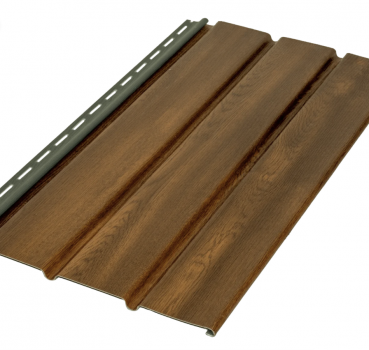
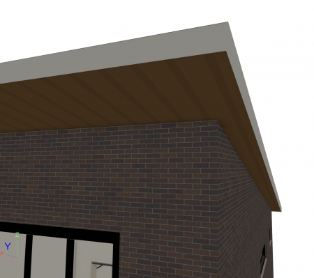
Attempting to create a more realistic wood grain vented soffit material while still preserving the existing Chief vent perforations and panel grooves.
Currently using the stock: “Vinyl Soffit – Center Venting” with “Blend with Texture” enabled.
However, the stock Chief texture does not contain much actual wood grain detail, so tinting it brown still reads more like colored vinyl than stained wood.
I would like to keep the existing vent perforations and soffit geometry from the Chief texture while also achieving a realistic stained wood grain appearance similar to the attached product image.
What is the best workflow for accomplishing this in Chief?
-
22 hours ago, DBCooper said:
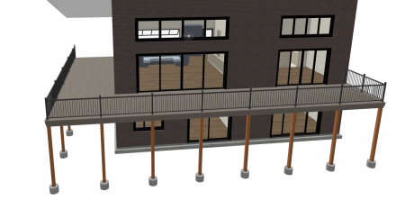
Why did you make an invisible wall that is not a railing?
Mostly because I was trying to avoid reintroducing a wall issue I previously worked through with Chief Training. During that session, I was instructed to use a railing wall in that location as part of the workaround to eliminate a hole that was appearing where the deck and wall intersected. Since the workaround resolved the issue, I was hesitant to remove that wall entirely and risk recreating the problem.My thought process was that converting it to an invisible wall and unchecking “Railing” might preserve the corrected wall behavior while functioning similarly to a Straight Deck Edge. Clearly that assumption may have been incorrect.
At this point I will probably submit the plan to Chief so I can determine whether this is expected behavior, user error, or a software limitation/workaround interaction.
-
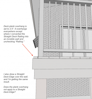
I’m running into an issue with deck plank overhang in X17 and wanted to see if anyone has encountered this before.
My deck plank overhang is set to 2.5”. The overhang generates correctly around the deck except at one location where I converted a Straight Deck Railing into an invisible wall and unchecked “Railing.” I also tried drawing a Straight Deck Edge over the wall and get the same result.
At that location, the first deck plank stops flush instead of maintaining the 2.5” overhang.
Is this not possible?
-
30 minutes ago, Joe_Carrick said:
Select the Wall and open the dialog. Then select the materials tab
That is what I thought, but for some reason I don't see a color listed.
-
9 hours ago, Joe_Carrick said:
Put a 1/16" thick interior & exterior layer in the wall type.
or specify a wall covering in the room.
Then select the paint color from one of the paing catalogs as the material
Thank you, @Joe_Carrick I appreciate the response. I must not have communicated my question clearly.
I am not trying to apply a new paint color to the wall. I am trying to determine what paint/material has already been applied to an existing wall surface in the plan.
I’m working in an older plan and cannot remember what paint color/material was previously assigned to a particular wall. Grateful for you.
-
What is the fastest and most reliable way to identify the actual paint/material currently applied to a wall surface?
-
9 minutes ago, Alaskan_Son said:
It sounds like your using a Temporary Point
You are correct! Thank you for your help today! All fixed and Copy/Paste Hold Position is working correctly! Grateful for you.
-
1
-
-
9 minutes ago, Alaskan_Son said:
Select that same Point Marker
Thanks Michael. That explanation finally made the workflow click for me.
For some reason I am struggling to actually select the Point Marker itself. I can click it multiple times and eventually the dialog opens, but I cannot seem to get it into a visibly selected state so I can copy/cut it to the clipboard.
I also tried selecting nearby objects and tabbing through selections, but it does not seem to pick up the Point Marker.
I understand the alignment concept now, I am just stuck on how to properly select/copy the Point Marker itself in X17 on Mac.
Thank you again for your patience and help.
-
23 minutes ago, Alaskan_Son said:
relocate everything in one of your plans to match the same coordinate location as your other plan
Thanks @Alaskan_Son I am struggling.I placed a Point Marker on one plan. Is it right that I select the other plan with the Edit Area to relocate it? I don't understand where I find the coordinates so I can coordinate the location so it's the same as my other plan. I've used Point to Point Move to move objects but I'm unsure how to use with coordinates.
-
I have two separate plan files with identical footprints in X17. I am trying to copy doors and windows from one plan into the other using “Paste Hold Position” so they insert into the exact same wall locations.
However, the pasted objects land far away from the building instead of inserting into the matching walls. I eventually realized the two plans are not located in the same coordinate/origin position within the drawing space, even though the footprints are identical.
What is the best workflow for aligning two separate plan files so they occupy the exact same coordinate position/origin location?
The goal is to reliably:
Copy → Paste Hold Position → have windows and doors automatically insert into the matching walls in the second plan.Thanks in advance for any guidance.
-
On 4/6/2026 at 6:46 PM, Renerabbitt said:
also see video
Hi @Renerabbitt
I was able to watch your video in another browser. Thank you so much.
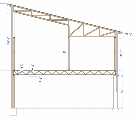
I scrapped my other plan and started over, following your suggestions. I set the walkout wall to “Stop at Floor Below,” created the two breaks on the east and west walls, and removed the pony wall.
However, when I follow the steps to check and uncheck the monolithic slab, I am not getting the same results.
Here is before Checking monolithic slab:
Here is what I get after checking and unchecking monolithic slab: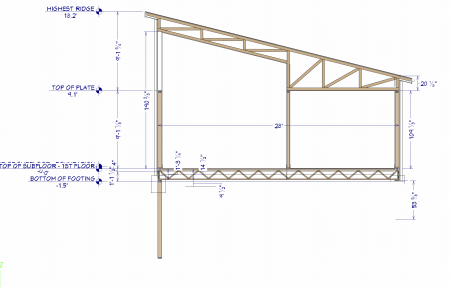
If you or @Alaskan_Son would like to investigate the plan and possibly point out what I might be missing, I would appreciate it. In addition to the issue above, I am also having a problem with the tall wall not extending to the underside of the roof truss.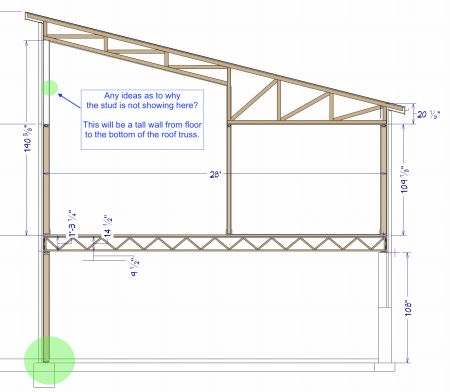
Grateful for any feedback. -
15 hours ago, Renerabbitt said:
I think it is,
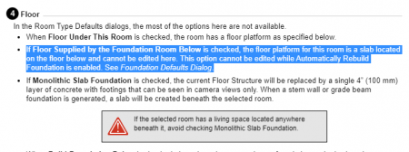
I’ll be honest, I read that Help text several times and it just didn’t click for me.
In my head I was trying to fix wall behavior in the Room dialog, so I wasn’t connecting that setting to what I was seeing. Since the description focuses on the floor platform, it didn’t lead me to think it would affect the walls or that unchecking it would fix the issue.
I didn’t realize that with that option checked, the floor and related foundation pieces are being taken from the room below, so changes I was making in this room weren’t having any effect.
That’s where I got tripped up. Thanks for pointing this out, now if I can remember it going forward


3 Way Switch Between Floors - Stairs
in General Q & A
Posted
In X17, I place both switches on the upper level at the top of the stairs, and then adjust the height of the switch that should appear at the bottom of the stairs. I add a comment to the switch and turn on the Comments column in the electrical schedule.