

SHCanada2
-
Posts
1592 -
Joined
-
Last visited
Content Type
Profiles
Forums
Gallery
Posts posted by SHCanada2
-
-
1 hour ago, DefinedDesign said:
Here you go
Is this more what you are looking ofr
-
6 hours ago, NeilofOZ said:
but need to place some
on the lower level which is over the entry & Garage.
it looks like a gable above the entry would be more feasible, as It does not look like you have enough room horizontally for a dormer with more than tiny walls
-
On 5/2/2025 at 2:56 PM, DK7000 said:
Manually moving the railing or deck edge/beams away from the homes framing and lining it up to the edge of the exterior brick wall is simply ignored and automatically snaps back into the homes framing structure
I think it you detach perpendicular deck walls from the house and run a parallel deck wall to the house about a foot away, and then move it to be next to the brick and then make it invisible, it seems to work:


-
10 hours ago, DefinedDesign said:
Since the two walls have different fascia heights, this results in mismatched top plate heights. I need both the top plates and fascia to align with the existing house.
see attached with 2 sections, both with same elevations for top plates, then I raise the roofs on the right structure and rebuild the framing. You can see the top plate stays the same
I must be missing something, you probably want to post the plan
-
i use it all the time because the CA truss heel height can only be set per plan, and not per roof plane
-
 1
1
-
-
when you build the roofs are you setting the same height eaves checkbox?
You could also just raise the roof planes using the transform replicate button, in the Z direction
As a note, the fascia heights will be different elevations if the roof pitches are different and eave width are the same, and you do not set same height eaves.
Alternatively to raising the roof, you could also change the width of the eave unitl you got the facia elevations to match...but that might not be desirable
-
1
-
-
decks here are attached to the rim board via a ledger board.
..I havent tried it but did you try running a deck railing along the house, parallel to the house wall? CA does not like walls really close together, so not sure how close you could get it
-
when you print to PDF choose 11x`17 and change the print options to not be "to scale"
-
1
-
-
just start typing at the bottom of the page where it says "reply to this topic"

-
1 hour ago, Builder921 said:
Appears the only way to respond is using the "quote" button???
you can also highlight what you want to quote and wait half a second and a little bubble should pop up "quote selection

-
 1
1
-
-
you probably need to post the plan
-
1
-
-
above previous thread has some statistics
also depends on X16 vs X15( or earlier) for number of samples
-
is this on a laptop? If so, the laptop will typically constrain the GPU when on battery.
What version of CA are you using?
-
7 hours ago, Kbird1 said:
basics of PBR as it isn't a single click and boom you have "photo" realistic Camera Views.
its 5 clicks to get something decent for interior
") , background intensity, sunlight intensity, exposure, brightness....and make sure to add some lights
, background intensity, sunlight intensity, exposure, brightness....and make sure to add some lights
-
6 hours ago, CharlesVolz said:
Placing the terrain on Floor 0 prevents cantilevered building areas like boxed windows on Floor 1 from cutting a hole in the terrain.
also what I do(create on lowest level I am working with). It becomes a bit of a PIA when doing houses on sloped terrain, as the garage is typically on a different level, as are main floor cantilevers. This is where the reference display should be used (or create polylines and duplicate to different floors....I've done it, and don't recommend it). If you do not do either, you can be stuck guessing where to draw the driveway to (because you cannot see the garage on the foundation level)
-
I did an interesting test yesterday.
I measured, I also received the realtor floor plan (which is iguide, which is a lidar scanner/photogrammetry setup in each room. I think realtors pay 3rd parties about $400 for a full house scan using this hardware and software), and cubicasa on my phone (which is a photogrammetry app and cost $10).
This is a basement which was interesting because although the exterior concrete wall is not jagged, the interior wood walls next to them differed from nothing by the stairs to 2x4 on flat on the south wall, to 2x4 everywhere else. Plus, there was a supporting 2x6 wall which runs down the middle. Neither of them caught the 2x6 wall down the middle as being 2x6. But the iguids caught the difference in wall width in the bottom, left, and by the stairs. cubicasa also has an incorrect width for the laundry room.
Both iguide and cubicasa mistook a light fixture above the toilet for a window.
Neither of them tell you about the bulkheads (which I drew in the CA plan)

so, for $10 its good if you do not need the accuracy (the use case for me is, customers are doing a basement reno and the city also needs a main floor plan "for their records" and as such does not need to be perfect). For iguide at $400, its better, but because it does not have varying wall widths, it does not calculate the gross floor area correctly (which here is to outside walls). Ironically cubicasa has the more accurate GFA in this case.
I'm still on the lookout for an app in which you can actually get the 3d model, in order to double check dimensions, and see anomalies before they (the purveyors of these softwares) create a floor plan...assuming they give you the unadjusted model.
-
1
-
-
there are tow different types of ray tracing. CPU, and Realtime.
open up a floor camera, edit it's settings and change to "physically pabsed

-
this would be a typical backyard garage suite here. I draw garage on floor 1 and specify stem wall depth. I draw living area on floor 2. I draw terrain on floor 1 I create a site plan that shows roads, sidewalks outside walls etc. and then use a reference plan if I have to show something on a different level
-
integrate with slices
...jk
might also be able to put a psolid across the entire terrain and then set its top to be the top of the terrain, with a thickness of whatever will be enough for your cuts.
and then model your terrain with the cuts, and then make another psolid, and then use the psolid tools to subtract (might have to cut the bottom to be horizontal). Havent tried it, but might be worth a shot.
I'm doing a very sloped lot right now and might try it in the next couple days. I have the undisturbed, current conditions terrain in another .plan file
-
At some point the O/S or other drivers will no longer work with software. Software companies have to then adapt and test their software with the next O/S/card drivers in perpetuity.
In my view, non subscription software has a niche, and that is where something is built that needs no improvements, only future O/S support. The PDF editor I have is in this category. All I need to do is edit the occasional text in a PDF. Do I need to pay adobe $311/yr for that? No, so I will pay a one time fee to others(currently around $75), and when I need to upgrade to the the O/S that breaks it, I will pay another $75. So my annual cost is $15/yr or 5% the cost of Acrobat. A lot of these companies that have these types on non subscription software have multiple pieces of software. So what they do, is have them in "maintenance" mode, where they will make enough money selling a few here and there, and then get a bump when the O/S no longer supports it, or some standard changes, and they make some money off paid support and ads on their websites.
But CA is not a simple product, and as far as I can see is in a fast moving market. This means they need to add features every year to keep up with the competition plus all the backlog of requests. And because of the complexity they need a support organization behind it.
Perpetual models also work for companies that have a large market to go after, but even they need to plan for what happens once that market saturates. Perhaps that is the way it was when CA started, but is no longer the case
-
2 hours ago, robdyck said:
- a straight, consistently sloped top slightly higher than the high side of the terrain
- a straight stepped top, formed in even increments suitable for concrete form work
yes, that is more real life, I understood it to be a 3D solid, which is why I commented probably the better option.
52 minutes ago, Mark3D said:Is that what you want
I dont need a footing, but that is interesting. Did you just pull down the footing (if so I suppose the footing could be set to the same width). Ultimately what I was trying to do was while I was adjusting the terrain, the wall would come along with it, but keep the bottom (below the terrain flat). Ironically in the end for this project, the terrain region was almost flat, so a 3D solid with a terrain break would have worked just fine.
But it did get me thinking for the next one how could I do it dynamically.
For this one I just put in a CAD box masking the ugly below the terrain terrain retaining wall, and for the moment, have yet to step the bottom. But I had to send it off Thursday so it went like that.. (...the workaround 3rd option..which is not my preference going forward)

-
5 hours ago, Mark3D said:
If you are still using retaining walls make sure the default top and bottom are selected as if you have adjusted the wall top or bottom chief will no longer auto adjust there top or bottom positions to match the terrain
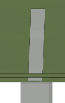
It looks when I made the, change to the bottom, only the bottom check box deselects. The top remains checked. If I move the terrain down say 20", the top still moves with the terrain but the bottom does not. see below
But is there a better option? A solid would needs its top changed to match the terrain, and in thinking about it maybe that is better as one could step the solid like a real wall, and if the terrrain moved up and down as a whole, the solid would move with it, maintaining the bottom of the wall.
...per usual... a couple options...each with their benefits and drawbacks

-
also interesting OOTB has footing...good to know
-
actually if one uses the red handle to move to the right, it can be done in 3 moves


Inconsistent Fascia Heights on Hip Walls Within Same Room
in General Q & A
Posted
where do you see that? I do not