

SHCanada2
-
Posts
1912 -
Joined
-
Last visited
Content Type
Profiles
Forums
Gallery
Posts posted by SHCanada2
-
-
what is quite interesting is it says it takes a measurement across the room as well, and can see if it is a cabinet or washer or... so it must be sanity checking its own wall measurements with this across the room measurement. In theory I would think that would improve the whole stitching problem
-
ironically, their demo picture shows the person measuring the wall between 2 cabinets:

but their how it works video says it needs to see the wall corners.
never trust marketing!
-
locked layer maybe. i'd select the all layers on layerset and then see if you can delete them. another possibility is a referenced layerset
-
4 hours ago, mtldesigns said:
Rob, I love that style of architecture.. you know its Canada when you see a hockey goal in the cul-de-sac.. "Car".. "Game on"...
and you know its southern Alberta circa 1990 to 2010 houses when the only trees you see in a suburb are columnar aspens..
-
7 hours ago, robdyck said:
I'd like 100% photo realism and a sunny day.
interesting how it first put the front yard tree behind the house. And it almost got the fence house connection right, pretty close. although it looks like the house is bigger that it was at the peak in the original. curious, can you tell it to make it smaller maintaining the aspect ratio?
-
There has been a lot of discussion on this, and I think the end result is as you do it above (make copies and keep log of changes) is the best way
-
 1
1
-
-
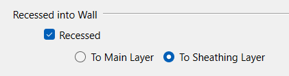
The core catalog E21 shows proud for some reason
I think I either fixed this before(as the "correct" E21 door is in my user catalog, shows as E21A int he video ).
I do not see a setting, and simply changing to the E21 Door, you can see in the preview that it pops out.
Is there a setting I am missing. They both show as Reccessed->Sheathing layer:
-
2 hours ago, ChiefHassanacif said:
Look, I am not telling you to buy it. I have tried it on my projects, and it gave me results far better than generic AI, likely because their models may be trained around our industry.
I'm not suggesting you are...just trying to find out the differences that make an impact. If you saw some worthwhile differences, that is good enough for me to give it a whirl
-
sure I'll try it out on my brother's. send me the beta link.
At a few hundred dollars a month, one question I would have is what to I get better than a generic AI, standardized forms maybe?
-
you might want to try the chatroom forum. navigate first to "home" at the top left
-
i was just about going to ask if I get a money back guarantee, and then I saw this:
Always cross-reference the output with the official municipal code for permit submissions. The analysis is designed to accelerate your research, not replace the final legal review.
...never heard of a "legal review", but regardless what it looks like is a AI tool that summarizes the zoning bylaws for a specific zone.
My brother just tried a different AI on the city's feedback on his proposal, and I would say it gave a decent start, but certainly not anything "intelligent". I.e. the City has a statutory document that states that for lots that are more than 20% slope, it needs geotechnical, but he AI is not intelligent enough to figure out from the survey what the lot slope is to see if the rule applies
-
2 hours ago, johnny said:
except if you're changing an existing plan with already different variable heights (which for us is most homes). Then, the select all roofs and add depth keeps everything the same in a relative nature.
thats kind of why I use it, once I have the roofs correct, I just go around and raise or lower them using TNR for some finer adjustments like trying to avoid another roof, but I do set the heel correct for the majority of the roofs first in the build roof dbx, so there is less chance I have to change it ...if I know the heel height to begin with
-
5 hours ago, johnny said:
As I understand it, Chief uses the "attic" profile to fill in with truss/web parametrically, and whether or not you raise the roof profile or go through the menu options.... its basically the same operation. If i'm wrong and there is some other reason i'd actually like to know.
raising the roof using the TNR to a 12" heel requires one to do the math of 12" minus existing heel height, and then that number is put into TNR, so I think doing it the other way (through defaults or the build roof dbx) is simpler
-
4 hours ago, CharlesVolz said:
The easiest way to do this regularly, like most things, is to set up your defaults correctly before you build your roof planes (including ceiling heights and roof structures).
This has the limitation of only one heel height globally. If for instance one is doing an addition, and the customer wants a heel height of 12" for the addition, but the house only has 4" heel height, you will have to adjust either one or the other manually..or perhaps although I have not tried, build some, mark them as edited, then build some more with a different heel height. I find it simpler just to set the heel height for the most roof planes that have the same heel, and then TNR the others to the desired heel height,
The other example is an unheated attached garage. It does not need the heel height for the insulation required here for the living space, and IMHO, a garage starts to look odd with high heel heights. As such I always set the garage to a different heel...manually
-
if it is an auto generated roof, and you specified heel height at 12", it should build them like that, although I typically have to build all framing to show that, as I have auto build shutoff.
If you have one or more manual roof planes, when you build the roof from the build roof dialog, make sure the check box is off for the edited and manual. CA will build an auto roof over a manual roof, so you may have two roofs in the same(x,y plane) location. You will then need to delete the auto roof.
To adjust the manual roof planes, as johnny says select the roof planes and use the TNR box to alter in the Z direction
-
the other thing I do is if you are only moving/removing an interior wall or two, I will use plines for these walls instead of walls, then turn the layer on and off. but that doesnt work so well if there is currently a door in the wall
-
multiple files is best IMHO. layersets method falls apart as soon as there are walls close together. you can try using no room definition walls if you want to give it a go.
I do the as built, and then create copy in the project browser, and then rename that copy as my as built.
-
 1
1
-
-
4 hours ago, robdyck said:
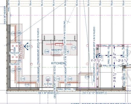
I think you have the wrong layers displayed for that function. If you have Walls, Layers turned off and if you do NOT have Walls, Main Layer Only turned ON, you cannot manually hit the wall main layer. That's what I think is going on there, but I could be wrong.
i'll double check, but auto dimensioning with the layers on as shown picks up the corner I am trying to dimension to, implying it is the main layer
5 hours ago, Alaskan_Son said:You aren't releasing you mouse button far enough from other object. To snap to your wall's main layer when there are other potentially conflicting snap point nearby, I often find the need to release the mouse button much further down the wall. It will still ultimately measure from the end of the wall, but you release the mouse button in an area where there are no conflicts.
I'll double check this as well, it was a while ago, but I think I tried that to, but not all the way to the top where it intersects the other wall.
I'll give it a whirl, thanks both
-
also related:
watch the levels carefully, or you will go crazy changing on floor, which then changed another floor, so you go to that floor to change it, and then it changes the other floor.
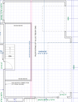
CA also has no concept (that I know of) of a split ceiling in a room, such as:
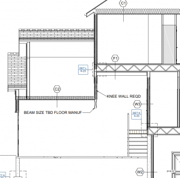
so you need to make an room using invisible walls (shown as walls below)in the garage that matches the room above:
-
6 hours ago, PitMan71 said:
Just trying to confirm whether this is a known behavior
yes, it happens. as rosco mentions usually because there is another room or the rooms do not line up exactly. For instance for a bonus room on top of part of the garage, you would draw invisible room in the garage that matches the room above
-
1
-
-
you might want to log a ticket with support, I'd be interested in seeing what they saw.
I have had similar issue but not to this degree
-
all layers on: like Michael indicates, I do not see them ...and turning off layer "cameras, wall elevations" does indeed turn the two below off completely
-
or a video of what you are doing to turn off and on and to populate
-
1 hour ago, Michael_Gia said:
If they have the AutoCAD file then they can measure whatever they want.
Anyone else do this?
some engineers and interior designers ask for this from me.
I just export it from CA and send it along.
For the truss people, they have never asked for a DXF or DWG file. ...that said they have made mistakes more than once, but it wasnt because it wasn't dimensioned, it was just that they missed it or in one case, got an off angle wall incorrect


Recreating a Roof from a Google Earth photo?
in General Q & A
Posted
roofr.com I think does it