

SHCanada2
-
Posts
1592 -
Joined
-
Last visited
Content Type
Profiles
Forums
Gallery
Posts posted by SHCanada2
-
-
5 hours ago, ComputerMaster86 said:
Based on my experiences it does seem like Chief will listen and take in people's suggestions. However, just mentioning things on the forum doesn't always seem like the best way to get Chief to acknowledge the suggestion.
Outside of the beta program, there are two methods, tech support and the suggestions forum. If tech support is the speedier way, then CA should publish this.
I will ask the question to tech support, hopefully I get an answer.
-
4 hours ago, VHampton said:
As for the project management feature, I’m not sure I see the need or benefit. Everyone has their own system for tracking projects, and it’s unclear how this integrates or adds value—at least from a sole practitioner’s perspective.
After using it for a month, I find it is quicker, and clearer as it is all right there. But I also have my own _template project I created, so I just copy that for a new project. Where before I would have to go in and link the layout to the plan. Works nice to see as built and different plan options
4 hours ago, ComputerMaster86 said:I am not trying to stur the pot but, are you guys making your requests known to chief by using something like the beta reporting tool?
I logged the stair problems in the suggestions area, as requested by CA.
-
If you have the floor plans and built the model in CA, normally I will use the TNR to move the roof in the Z direction to match existing elevations, as normally plans do not have heel height.
Or if possible, rebuild the roof with different heel heights until they match, but heel height is global for the plan, so if you have different heel heights, TNR will work instead
-
import the pdf into a CAD detail, (or on your plan) and scale the drawing using a known number on the pdf, or assume a floor level height 8' or 9' as the client tells you, and then scale using that. then use the CA measure tool to measure the height
I do mostly reconstructions, the above works quite well for me
or generate your own elevation and superimpose the PDF on top of it.
-
As someone who does most of my projects in a few hours, there was not a lot of feature changes, so far as I have played around, to improve my efficiency (except project management mode). The new project management mode is quite nice and is quicker for starting a project and using reference display sets. Showing Stairs on either level feature will be nice for garage suites and site plans as well as the walkthrough improvements, when I do them.
I look forward to the webinars to see what I may have missed. There are always some good nuggets to pick up
-
 1
1
-
-
1 hour ago, DBCooper said:
haven't figured out a way to make this work on room areas directly though so I usually end up make room polylines instead.
You can drop a text box in the room with a macro. The macro is in the link above
-
a search for metric room area yields:
-
3 hours ago, builtright3 said:
Just my thoughts because I have to keep it simple and everyone on the same page to save confusion.
I tried that once, then the development authority told me to put them on the plans to get them approved
-
and if you want a dutch / reverse gable You can take dougs two roof planes above the entry door and move them using the transform replicate tool in the Z and Y directions. Then collapse the main lower roof to where it was,. and then draw a second floor wall below the gable roof planes, with the property roof cuts wall at bottom

-
that is handy, where today I just guess
-
Are you looking to put a gable there or a dormer? I dont think a dormer would fit.
Post the .plan file
-
6 hours ago, Rookie65 said:
%width%x%height%
or use %width"W x %height%H
then there is no debate
-
14 hours ago, John_Charles said:
I just want to raise the roof height to match the surrounding structure without losing the ceiling height of he smaller room
select the roof planes and go to transform replicate, move it in the z direction
-
2 hours ago, DenisonDrywall said:
I was unable to attend the webinar. so where are the project management files being saved at? I can't find them. I want them in a specific folder so I can find them when i need them.
in project management mode, the files are not accessible. If you want a copy you have to export it...but it is a copy
-
what do you want the roof to look like? Normally I will raise the roof or alter the existing roof to go over another part of a building
-
On 5/7/2025 at 8:35 AM, Ange822 said:
Every time I seem to drag the layers back, it seems to just go back to where it was?
I've had that problem many times and thought it was just me. If you do find out what it was with the wall intersection tool, please post the solution, thanks
-
not sure exactly what you are trying to do, but you can set the eave width on the wall if you do not want it to protrude beyond the wall
-
Managed projects has multiple ways to be used based on your desired workflow. Common Documents seems to be for warehouse type template plans
-
On 5/6/2025 at 5:52 AM, DefinedDesign said:
or why the attic wall over the stairs isn’t resolving the gap like it did in the other location
I'm not sure what the purpose of the wall in the middle of the stairs is?

If you delete it, it works

as long as you set the attic wall to "roof cuts wall at bottom"


-
lower the roof planes using the transform replicate tool, or make the eave width larger
-
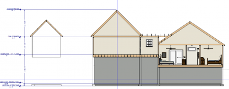
On 5/3/2025 at 7:33 PM, DefinedDesign said:
Existing Home
as well, if this is existing house, to be accurate you would need to know the heel height or difference in top plate to bottom of fascia If rafters, the birdsmouth depth is not certain l
Below you have
On 5/3/2025 at 7:33 PM, DefinedDesign said:I need both fascia tops to align with the existing house’s fascia height of 94 5/8”.
is that as measured from the top of subfloor on site?
Typically to know for sure, one would have to go into the attic, or open up the soffit or do some math on relative heights (such as measure from top of window to eave, then measure from ceiling to top of window inside)
-
one side of your gable has 12" overhang while the other has 18"...not sure if that is intentional

-
3 hours ago, DefinedDesign said:
The roof pitch on the main house is 12:12 the pitch on both roof planes on the connecting room needs to be the same, preferably around a 3 or 4:12.
your roof pitches are 8:12 and 3:12 when auto built:

the bottom wall has it as 8:12

-
It still shows correct top plate. after the rebuild of the roofs, the proper way to eliminate roofs is to use the roof intersect tool.
the one I modified is too big to attach, but deletde all roofs but the main tw0 over the breezeway and then, modify those 2 to meet the garage


Roof
in General Q & A
Posted
z moving...one of the first great tidbits I learned from @solver before he left the forum