
.jpg.67a2c38f009a8fe144bb2ed24f34e17a.jpg)
mtldesigns
-
Posts
1191 -
Joined
-
Last visited
Content Type
Profiles
Forums
Gallery
Posts posted by mtldesigns
-
-
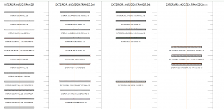
I have to totally agree with DBC, but I am anal on details. I have over 130 different walls I keep on a library drawing to drag and drop on my projects. It really is easier to do this the right way than to have more work for you at the end. Just for example, a typical con doc set, is you dimension to the studs. A nom wall your dimensioning to the sheathing, the trades probably wouldn't want that method.
Are you doing this for brochures or something?
And good luck, welcome to the club. Lots of knowledge here, I've been using Chief since X6 and I still learn something new everyday.
-
 1
1
-
-
1 hour ago, winterdd said:
Why are more doors showing like this in plan view
Just like Keith mentions.. looks like your framing for headers is on.
-
1
-
-
3 hours ago, decorators3 said:
Ha ha..i was tryng to keep location private...such is life!.
No worries... lol. It will be our little secret.
-
 1
1
-
-
3 hours ago, SHCanada2 said:
The simplest way to scale is: if there is a dimensions between two points on the pdf, you do a point to point measurement in CA (after you have imported the pdf), and then do a ratio of that measurement with the one on the PDF
I do it this way as well. But I will try the suggestion that DB linked next time.
You probably will need a contour map as well. The property details are nice, but that lot has a deep slope per Google Map. I am not sure on what you need to be doing, but if your designing, looks like having the contours will be a MUST!

-
1
-
-
2 hours ago, DanielleDubuc said:
draw 2 doors one behind the other in the same casing
Yep, just like Jim states. I always create this door to the side, make any changes (like turn off all casings, jambs, and lintels). Cut and paste to its new location. Easy Peasy.
-
Dang..................... some steps there for sure.
-
10 hours ago, ConnorE said:
This is the only time the new Ganged Blocks are created automatically.
More of a follow up on your response Connor, and its more of just a curiosity thing. Why in 16 does it do this automatically, but not 17?
-
9 hours ago, PitMan71 said:
Is the screen shot from X16?
NO that was a X16 file opened up into X17.. it now is a 17 file...
So I wasn't crazy... and I remember somewhere seeing this.. prob the X17 preview vid. Thanks. I am ganging away now.
-
Ok I thought I was seeing things... or saw things IDK. I opened a plan I last opened and saved in x16, and my switches are "ganged" as a block. I like this, but how did this happen? I know I didn't do it on purpose.. and if its a X17 thing, why are the models I am working in 17 not doing this? I don't see any setting for this kind of thing.
-
38 minutes ago, HDPWestCoast said:
SAVE and MAKE A COPY and for the life of me
I see "Save As" under the File pull down. I also have mine set up not using the project management tool too, so I don't know if that is different. Can you make a copy via explorer?
-
The projects I was real close to being competed in X16, I finished in 16. I did have a couple others started in 16, but then saved in 17, and I have not seen any issues thus far.
That bears the question.. how many versions should we keep on our PCs? I have 12-17.
-
1
-
-
6 minutes ago, Mitchellopolis said:
The Roof Planes display setting is unlocked, along with all other roof layer related settings.
can you share a screen grab of this?
-
On 12/27/2025 at 11:22 AM, dakwest said:
CA will not let me because of the interior wall even though the window is above the room in the Gable
Is that wall and attic wall by chance and is it needed?
-
3 hours ago, Tryingtobezen said:
It is kicking my butt
This will be fun.. and thanks for sharing. This is quite the roof line, I lost count on how many roof planes and all the different pitches. But to answer your question on not having a "upstairs layout", I don't think you need one. The shell should get you what you need to start with. By looking at this 39 page attachment, with measurements, pitches and photos, I would think you could do this. Page 5 gives you all the wall dimensions.. draw that profile first. Create second floor by using the same profile from below, then adjust accordingly by using the pictures. Page 9 gives you the soffit depths. Pages 11-18 give elevation profiles and more dims. On page 32 a more detailed roof layout with ridge and valley dims. Lastly, all the pictures of this house can get you a good idea on how exterior walls align, for example over the garage. It's a lot, but I think you got this, just do one step at a time.
Curious on what "Hoover" is and what they do? I like this document BTW...
I am assuming your using Chief Premier, X17
-
1
-
-
18 minutes ago, Jyknight93 said:
who has ready-made stock plans available
Your looking for a pdf plan set, not the Chief model -layout, right?
Something like the attached?
-
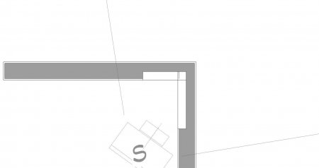
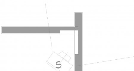
2 hours ago, Fotis1960 said:
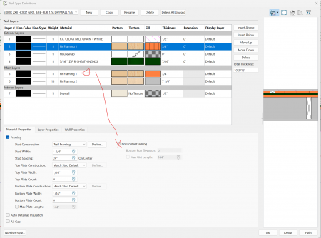
How do I create this wall?
A couple of questions for you. First, are you going to provide a wall framing detail showing the studs OC dims? And are you going to run a report for materials and cut list? Are these post a true 6x6 or are the 5-1/2 x 5-1/2? I asked this because I did have a home where the post were a true 8x8s. That changed my approach some. The few I have done the builders could have cared less where I showed the studs, so I located my post per the spacing requirements, then I drew a wall, a normal wall right on top of it, with the post being centered with the framing. I am assuming the girts are on the outside of the post of your build which makes it a little different than what I had to do. With the post of mine being true 8x8s, I had to put girts inside the post to post to make up for the difference with the 7-1/4" wd studs. Builders Idea... and it seemed to work since their living in it now.
On the second picture, you'll see I just placed my wall in-line with the post. I did place some "end view" of stud cad blocks in my floor plan, for understanding how I wanted this to frame without doing a framing plan. Also, you have to keep in mind the requirement for the kings and jacks framing at the windows and doors, so that was another reason I placed those stud end views.
Hope this helps...
-
2 hours ago, DBCooper said:
I would encourage you to give your posts better titles because I almost ignored this because I thought you wanted to hire a draftsman instead of ask a question about the program
SAME HERE
-
8 hours ago, RichardD said:
convert it to its elevation
I believe so Richard. Chief will not recognize those lines as anything but lines. The need to be elevation lines to work, IF your trying to show the contours in the 3D model.
-
1
-
-
7 hours ago, Ed_Orum said:
Can I draw it as a separate plan, with my garage defaults, but then send it to the same Layout as the main house without one plan's defaults and preferences trying to impose itself on the other plan?
I have before without issues, I haven't tried it in 17 though.
-
I’ve had this come up before and have gone back and forth on the best approach. A few key questions come to mind:
-
Is the garage being built at the same time as the house, or before or after?
-
When you say the garage will not inherit any properties of the house, can you clarify why? For example, will it use different building materials, a different framing method, or a different construction standard?
-
How close will the garage be to the house? If it’s located a significant distance away on the property, it raises the question of why it would be shown on the same plan set at all.
One possible approach would be to reference the garage within the same overall plan set but place it on its own dedicated sheets, showing its location clearly on the site/plot plan.
If the garage construction is planned years down the road, it may make more sense to issue it as a completely separate package, especially since permits are typically time-limited and may expire before construction begins.
That said, at the end of the day, it’s generally best to accommodate the client’s request—as long as it’s legal, ethical, and doesn’t create downstream issues.
I do understand why the builder would prefer to submit everything at the same time; it likely saves both time and permitting fees.
-
-
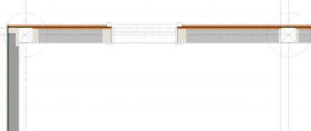
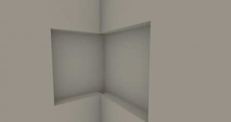
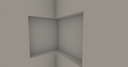
1 hour ago, Gary-Doski said:
similar to the corner window
Hi Gary,
I tried this on a 2x4 wall and got the same results. I'm thinking it has to do with wall framing, and that makes sense. When I change that wall to a 2x6, the niche filled in, except at the bottom corners (1 and 2 attached). However, when I continued either wall in the plan view, the whole box did fill in (3 and 4 attached)
.
-
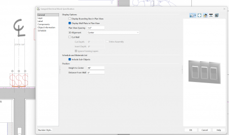
2 hours ago, ChiefUserGerald said:
enlighten me
Hi Gerald, Please see the very quick vid wo sound.
I don't know what version your running, but this vid was using X16
Basically, go to the roof build pull down and select Tray Ceiling Polyline
From there, draw your shape. Once that is determined, pick the outer "box" of that trey and the dbx will pop up. You can set this trey to be vertical or at a pitch (degree).
I hope this helps.
-
1
-
-
6 hours ago, Evolution said:
but I haven't figured out how to rotate it to place it in floor plan view
I made it a symbol, then once its in your user library you can rotate it. See the attached.
- make a symbol
- open symbol and rotate on the X axis
- don't forget to make it a 2D block
-
1 hour ago, JuanR2 said:
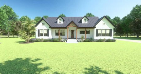
Does everyone spend so much time waiting for Ray Tracing and Videos?
No. 500 sample passes take about 20 to 30 seconds. The one attached took 25 seconds and that's with all the light on.
Maybe someone on here can explain computers better. Try ChatGPT and ask "how can I make NVIDIA RTX 5070 8GB, Intel i9 32 GB Ram go faster" . I just did, tons of suggestions.


Wow, how different AI makes renderings!
in Tips & Techniques
Posted
That does look pretty good Dustin.
I wonder how the crack in the concrete got there.. pretty cool affect, however a new garage shouldn't a crack yet. lol.