

yusuf-333
-
Posts
682 -
Joined
-
Last visited
Content Type
Profiles
Forums
Gallery
Posts posted by yusuf-333
-
-
Add lites in the widow dbx. or if that is some thing you can't achieve using lites, try loading custom muntins. custom muntins can be loaded as a cad block having the shape you desire and then load as. custom muntins(refer the help & ref manual for further info). if that doesnt work there is still a way to add window treatments. in window dbx, go through the window treatments and look at the options you have.
-
Are you using pony walls? if so, you have the setting there in the PW dbx to choose the default wall to show in plan view. that is what determines the situation to appear, if you choose the upper as the default.
Most likely the best answer, but still not sure.
-
It probably is bad architecture as I'm no architect. LOL. I think I will have to make some adjustments to my building. It was new, not a rebuild. I have been working on a copy of it, so I'll make a few changes.
Cheers and thanks.
Coralie
Ladycoralie, sure David and glenn has said it well, I will also give you a free offer of an hour session on Skype. please PM me your Skype name and I will let you know when I can do that for you.
-
just guessing, 2 options

-
 1
1
-
-
Considering how many people helped me with videos on this forum I felt compelled to make one for you....enjoy. Its pretty easy.https://www.youtube.com/watch?v=DVeuxItO-a4&feature=youtu.be&hd=1
Much appreciated!! very nice work.
-
Carter
lf you could have done this with P S, you pretty well know that chief uses image to simulate materials and patterns to show the vector views. But good job, with little peciency you can create the level of detail you need using C A.
-
seems some thing like this. though your request needs to be some more clear to exactly help.


-
Contact Graham and Rich, if you want to stick with chief. learn their great tips to save minimum 19Hrs&45min.
-
Chopsaw, Great video and your vocal is well with your mic.
I am sure you have a lot new stuffs to share.
keep up sir.
-
OK, so I can't leave this BMW symbol alone.
Here I replaced the cardboard cutout 2D trees with a couple
of Frog 3D trees (Sweet Birch I believe they are) and threw in
a stock Chief 3D Backdrop. Starting to get some really nice
interplay between the reflections and shadows.
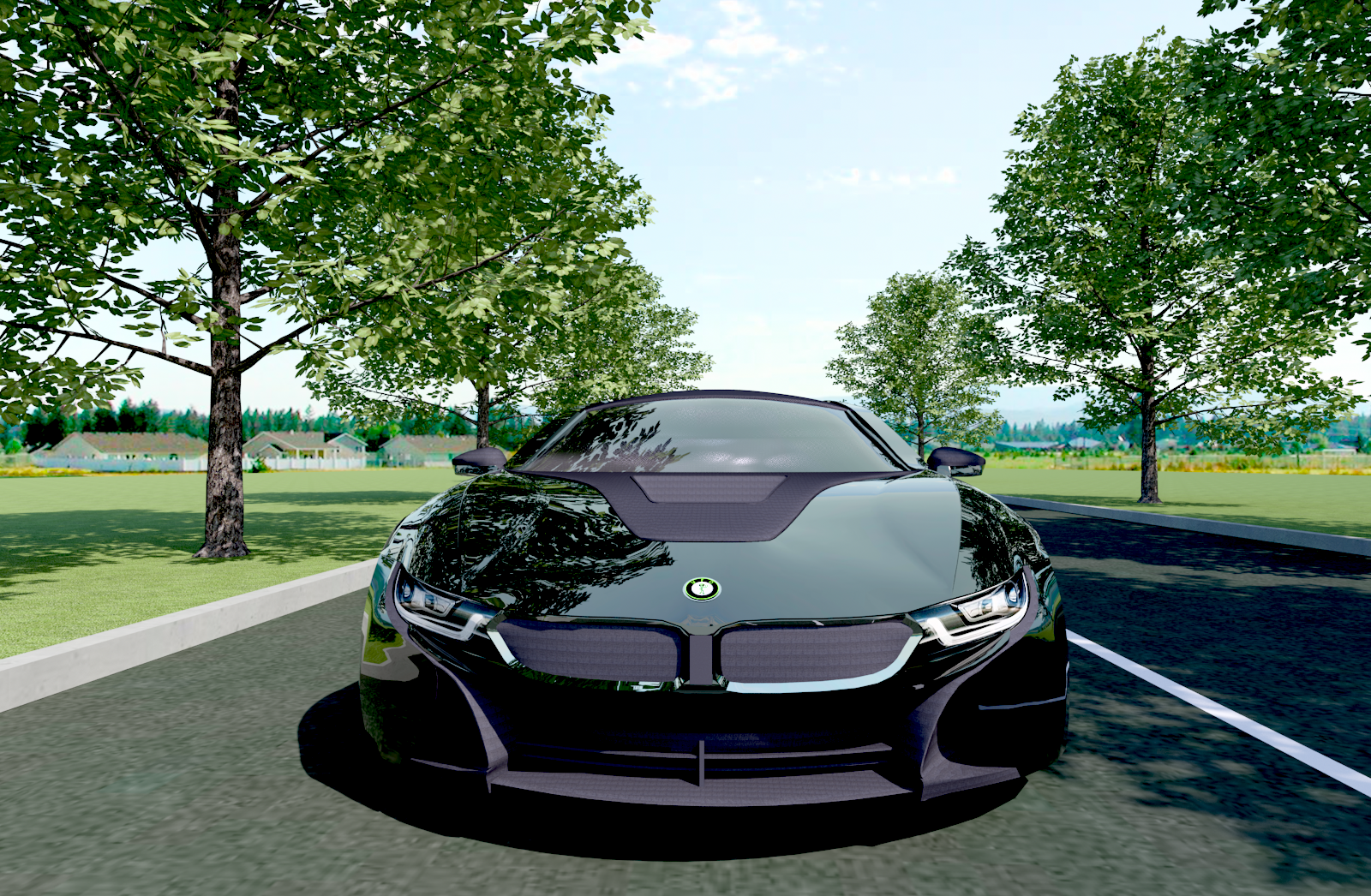
Check out the Carbon Fiber texture (Patent Pending). I think I
tried about as many settings as Edison tried filaments for his
lite bulb before I stumbled onto this look. I like the way the
"grain" of the weave runs in all the right directions and follows
the contours of the curves.
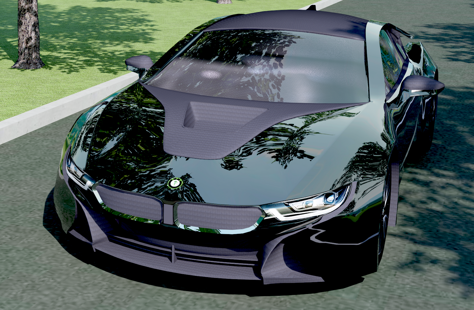
This is the look that the kids today called "murdered-out"
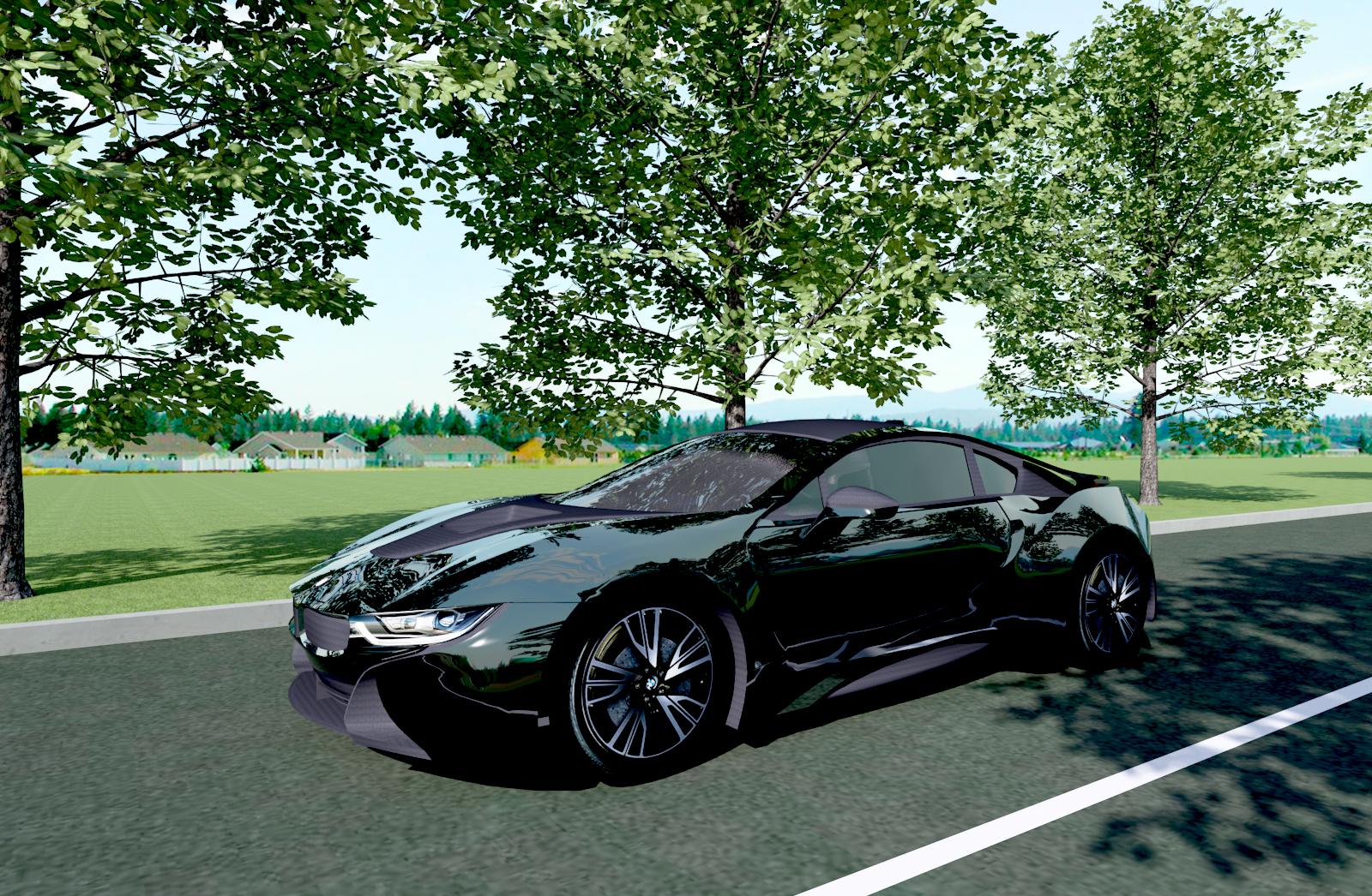
Personally I prefer something more understated... like this.

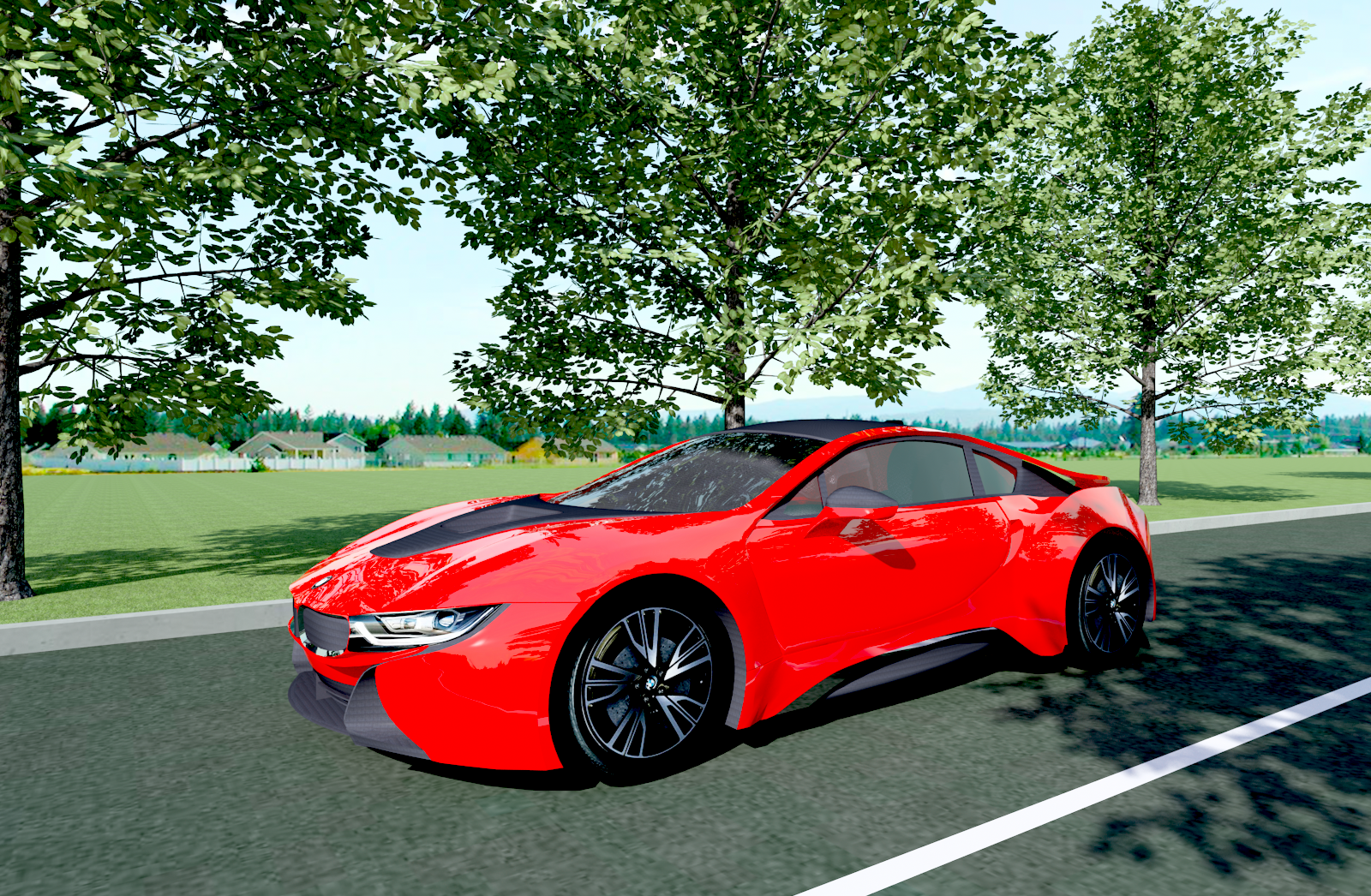
Ninety nine and a half won't do.... Got to have 100% Chief
Rich, your experiments are fantastic! 199%. The certified CA.T has gone the 100%, yet can't......
-
If you want to auto reset the wall height of specific wall, open property dbx for that wall and in structure tab there is "set to default height" button.
though not sure if that is one of the auto things you were asking.
-
Hi Guys,
Deedee with Chief Architect Training here. I got it pretty close. A few work-arounds with polyline solids and I have one small issue with a pony wall here still trying to figure out but it looks pretty good if I do say so myself.
 Give me a call if you want to learn how.
800-482-4433 Ext 3323
Good job Deedee, looks great. though not sure the time it took you to get those details.
-
Scott, that is cool. Here, 8 hours time difference, but I will try to arrange time in the future if possible. Actually there are times I am active even at your late nights, but working with my customers out there.Workshop summary: First I want to thank all who attended. If I learn one thing out of a workshop, I consider the time well spent.
I did a lot of the narrating in the beginning, and if I am talking, I am probably not learning.... but....
This is what I learned.
1. The Glenn Woodward Retaining wall/footing/cap method. This is akin to my request for the Super Pony Wall, but a bit more limiting.
2. Reinforced my believe that CA builds terrains with a few peccadilloes. This was confirmed when together we saw some "spikes" in the terrain for no logical reason and the only way to eliminate the "spikes" was to remove a select topo elevation line which should not of been necessary.
3. Chopsaw challenged me to import an ACAD TERRAIN file, and I was able to do this very quickly. The file I had included what I would call "smart" topo lines, meaning the imported topo lines had an elevation associated with them. How they did this, I do not understand, but it was very cool. To Chopsaw, I would share that particular file, but it is not mine to share, so I would rather not.
During the workshop, I wanted to run across some more CA terrain peccadilloes, but we ran out of time. The workshop was 2.5 hours long. I do not record these workshops nor do I want to spend the extra time required to process these workshops nor do I think anybody wants to listen to 2.5 hours of our banter. So if you are interested in the topic, you might want to find time in your schedule to attend if possible. We usually have some pretty heavy hitters who always have something to share.
If any of you other attendees learned something, please let me know. Thank You.
Regarding the points raised, I would like to say what I know about #3.
the smart lines are topo lines that had a Z value initially in the AutoCAD. there are various ways that could happen.
* by opening the line properties you can manually input the value of Z inside AutoCAD.
* if the .DWG topo were produced by other programmes that generate topo lines like, Eagle Point or similar softwares that can process data from Global Mapper or survey data. then the imported cad file has automatically those smart topo lines.
just a thought.
thanks and keep up the good works. we all, even those us power users really owe you and Glenn a lot...
thanks
-
Now Dennis, are you trying to get me in trouble?
In today's overly PC culture, using attractive young
women in your images can be a slippery slope. I'd
hate to offend anyone with the crass use of eye
candy to enhance my images. Not to mention that
hot and sexy are highly subjective terms.
That being said, is this what you had in mind?


Took the Bimmer to LaLa land.
"And those Hollywood nights
In those Hollywood hills
It was looking so right
It was giving him chills"
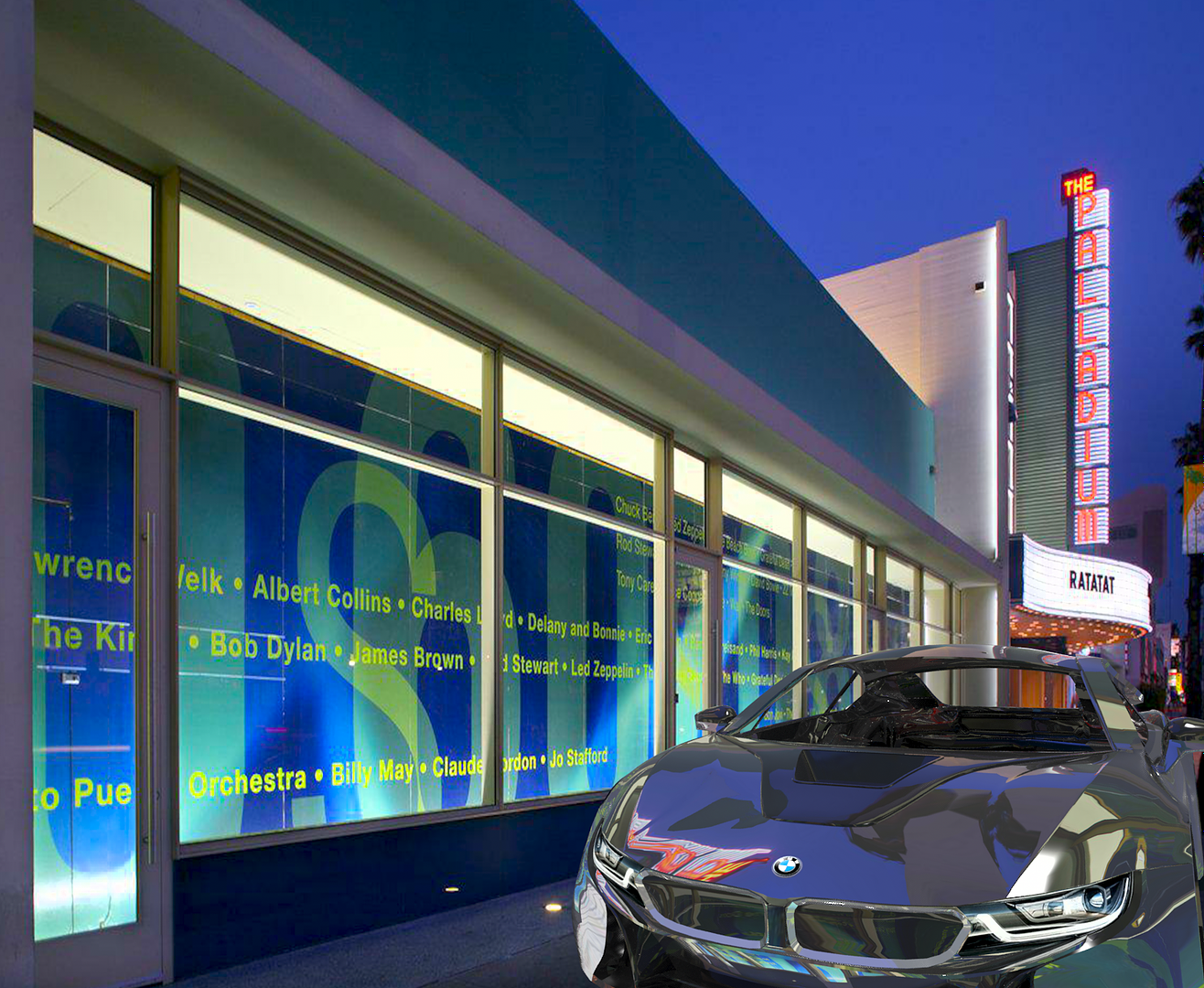
All Chief all of the time.
Rich, your RT are really awesome. Your secrets please?!
-
seems that you can achieve that one, by using the just a wall and a roof plane for the sloped wall. As Eric said, control wall height in elevation.
-
You could try two railings stacked on top of each other 1 32" solid Railing with 10 spindle rail on top with No Room Definition and No Locate. I am sure there will be other suggestions but I think this is what I would try first.
yes that is exactly the way, but also you can make a panel of your stacked railing and use as one railing wall for simplicity.
-
One additional idea to add to this:
You can also consider using multiple walls side by side in order to avoid cutting through the substrate layers. Something like this...
-Wall #1 might have interior finish layers, framing layer, exterior sheathing, and building wrap
-Wall #2 might have a black or exterior finish colored "shadow line" material for the main layer followed by your exterior finish layer(s).
-Your material region "grooves" would be applied to Wall #2 and again...the material regions would go onto their own layer and simply be turned off.
This way your details and model will be a lot more accurate.
Quick sample plan just to give you a very rough idea...
Perfect solution Michael.
thanks for sharing
-
Chopsaw thanks for the complements, and sure you are right 100%, with the same concept of transform and replicate tool, you should be able to do that using plolyline solids.Thanks Yusuf, That was incredible, you have such a great talent for this. I suppose to build with bricks you would use all the same principals with polyline solids?
thanks
-
Twisted structure using the wire frame method.
-
thanks Larry, I see Michael answered it well. I will post how to model twisted chimneys as the one attached using this wire frame method. I hope that will also explain more about how to.Yusef, Are the wire frames simple 1/16" - 1/8" molding p-lines set at different heights and shapes?
thanks

-
Thanks all guys, we all have learned a lot from this forum and I am really great full to those who have shared their knowledge with us all tought us what what what we know today.
thanks Glenn,Joe, Val and all of you for the kind words.
-
thanks all of you my friends, I am really happy, if that worked good.
Sorry about the sound, I will try to fix it.
-
Thank you.
At the risk of sounding like one of those power users who makes up work-arounds, the program can make pretty much any shape you can think of.
I still don't what a Ruby is though, so I guess I'm safe.
val nice one, only Dermot would take the risk, but just to help them see how great their product is. here is a new way that I can take the risk of modelling almost any shape that we may need in construction industry. this method is to be called the wireframe method. it makes use of 3d molding poly lines and chief's primitive tool. this enables us to model almost any shape.
here is a video on how to .....
-
3
-
-
try this in blank plan.
draw a wall and view the elevation camera.
draw a cad rectangle on the wall, using the elevation view you opened.
select the cad rectangle and from the bottom menu, select the "convert polyline" tool and tick the poly line solid radio buton. click OK, and a dialog box window will pop up, so that you can specify the depth of your created architectural object and even assign brick material using the material tab at the bottom of this same dialog box.
hope that helps. I advice you to try viewing video tutorials at chieftutor.com
that will help you to learn step by step of the basic lessons.


21st Century
in General Q & A
Posted
As rechard said, some one can help you, but still not clear what your problem is.