

rlackore
-
Posts
3036 -
Joined
-
Last visited
Content Type
Profiles
Forums
Gallery
Posts posted by rlackore
-
-
The roof tiles in your example are represented by a 2-dimensional Material (Chief Architect X11 Reference Manual, page 1023); Materials can use Material Maps (page 1024) to simulate a 3-dimensional surface using Bump maps and Normal maps; only specific Rendering techniques take advantage of these maps. If you want a true 3-dimensional surface, you need to use 3-dimensional objects or Symbols for the tiles.
-
I use Word. Text formatting and editing is easy. I have a master document that gets "copied" for each new job and I edit as necessary, then export to PDF for publishing. Making use of the "hidden" font attribute allows me to keep text without it being displayed or included in the TOC; "unhiding" allows me to include it at a later point in the job if necessary.
-
When I "improved" the material the Texture>Retain Original Aspect Ratio checkbox got checked unintentionally. Changing the material to 3x6 is easy, just adjust everything in the Material dbx:


-
Did you accidentally delete the roof openings (on the floor below)? When I recreate them, I get shafts:


-
For your inverted tile, a normal map is all that is necessary (my opinion). Googling 'normal vs bump map' will lead you to further reading. Here's a better version of the material - I removed the pronounced shadow from the left bevel so the fake shadow isn't biased to the left: inverted tile improved.calibz

-
-
 1
1
-
-
I ran my own test back in August using a Layout file with/without an embedded PDF (the PDF file size was 13 kb - not very large). I printed the output at 300 dpi using Chief's PDF printer. Here's a screenshot of the Layout page without the embedded PDF - the printed file size was 40 kb:

Here's a screenshot of the Layout page with the embedded PDF - the printed file size was 1,152 kb:

This was an increase of 2,780%. When I printed the page with the PDF obscured by a CAD mask, the printed file size was 1,153 kb, so even though the print engine wasn't required to render the PDF, the PDF still impacted the size of the printed output. I shared these results with Tech Support via a ticket, and was told the results of my test would be passed on to the development team. It was suggested I explore using other print to PDF options, but that Chief "cannot guarantee that everything will render correctly from our software."
-
1
-
-
Is she using Gmail within Chrome (or another browser), or if she is using another email client that aggregates all her accounts? If she's using an aggregator, maybe it treats attachments differently.
-
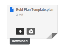
I don't know if Chrome and Gmail looks/works differently on a Mac, but on Windows you don't need to right-click the attachment, simply mouse-over the attachment and select either Download or Save to Drive:

-
Maybe find a different way to share files, such as Dropbox or Onedrive.
-
1
-
-
32 minutes ago, Chopsaw said:
Robert, That looks good but Is there a way to make that work for the arch and keystone ?
Sure, it can work for any situation if you're willing to create the necessary normal maps. Not easy, I agree, but possible.
EDIT: Maybe material regions (as Joe suggested) for the rustication joints with a normal map assigned to the material regions?
-
You can simulate the bevel with normal maps. Here are example materials that can point you in the right direction: HardiePanel.calibz


-
You can create a sign without too much trouble if you're comfortable using a graphic editor like Photoshop or The Gimp. The example below was created using Chief tools - millwork for the posts and polyline solids for the board - and using The Gimp to create the diffuse, bump, and normal maps from a picture I found online. The picture was low-resolution, so the result isn't the best, but with a higher resolution image you could get much better results.
Rendered in Chief:

Rendered in Sketchup:

-
11 hours ago, Ikedcr said:
If you are talking about the skinny profile of the brick where it meets the siding, .....
Maybe just a matter of using the Edit Wall Layer Intersections tool to drag the brick layer over so it terminates at the corner squarely:

-
You're correct about the batt insulation - it is an Autocad Linetype that isn't supported by Chief's Line Styles.
I don't know why Chief would interpret the same fraction incorrectly, but you could modify the text in Autocad with the Stack Properties before importing.
-
1
-
-
15 hours ago, robdyck said:
Looks good! 2 questions: which materials (and settings) for your grass and water?
The rendering was completed in Twinmotion; the grass and water textures are materials native to that program.
-
A couple of threads to check that may be of help:
-
Very simple pool, but this was my solution:
Roof Plane for the sloping pool deck with a Hole to cut out the pool shape.
Slab for the pool bottom.
Molding Polyline for the pool tile & trim, and the coping tile and cap.
Polyline Solid for the water surface.

-
1
-
-
This is a roof louver based on the Active Ventilation Products 14" Pop Vent. Rather specific, I know, but I needed one for a project.

-
2
-
-
Like Glen said; maybe you don't need a light, just an object (Polyline Solid, Soffit, etc.) with an emissive material:

-
-
You need to Backup Entire Plan so the textures are exported. Or just post the texture as a .calibz file.
-
Have you tried re-shooting the cross-section/elevation? Maybe it's a problem with one particular camera? Or you could post the plan for us to examine.
-
Chief's Reference Manual implies that if it's installed on your system, it should be available:

Have you tried rebooting your system after the codec installation?


Something New
in General Q & A
Posted
This old thread may give you some ideas: here.