

rlackore
-
Posts
3087 -
Joined
-
Last visited
Content Type
Profiles
Forums
Gallery
Posts posted by rlackore
-
-
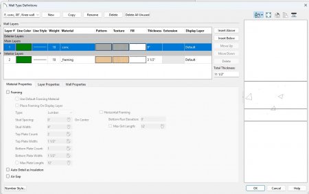
Another thought. With the new wall definition tools in X17, when you build your wall definitions, assign the "exterior" and "interior" wall layers to unique display layers, like this:
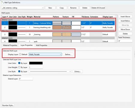
Here I assigned the Exterior Layers to Walls, Facade; then is any 3D view simply turn off the Walls, Facade layer and you will see what is underneath, such as the wall framing, or the restrained masonry infill, or whatever.
-
 1
1
-
-
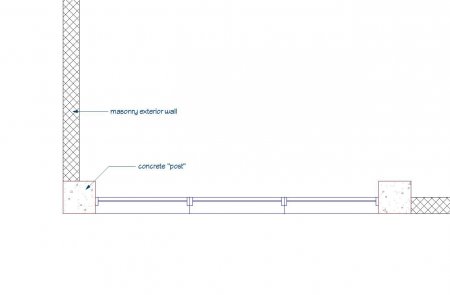
Chief Architect isn't well suited to RC structures with restrained masonry, so you will have to make some compromises. However, unless you need to show the RC structure and the infill in 3 dimensions, like your attached image, then I suggest setting up your floor and foundation defaults for the horizontal concrete elements, and your exterior wall types (with exterior cladding and interior finish) for the masonry portions. Show the vertical concrete elements in plan view by using concrete "posts" or by using a CAD object, and adjust your building sections, etc., with CAD objects.
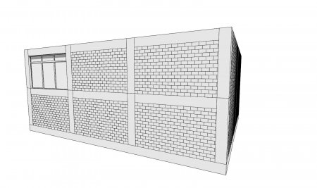
But, if you HAVE to show the 3D, it can be done by not including the exterior materials in your wall definitions:
-
 2
2
-
-
OP,
The plan file you zipped and uploaded is not the same as the your screenshot.
-
43 minutes ago, Joe_Carrick said:
We used to have the "UBC - Uniform Building Code" in California. Is your code derived from that?
No idea, but I doubt it. It was created during the Carter years but wasn't enforced state-wide until the 2000's. It's a Frankenstein: our UDC is written into the Wisconsin Administrative Code, so any changes are an act of legislation - much more difficult than simply adopting a model code by reference.
-
Wisconsin uses its own residential code called the Uniform Dwelling Code. It's quite abbreviated compared to the IRC. Whenever there is talk of adopting a model code, there is tremendous resistance from contractors. It's also very difficult to enact code changes due to a convoluted legislative process.
-
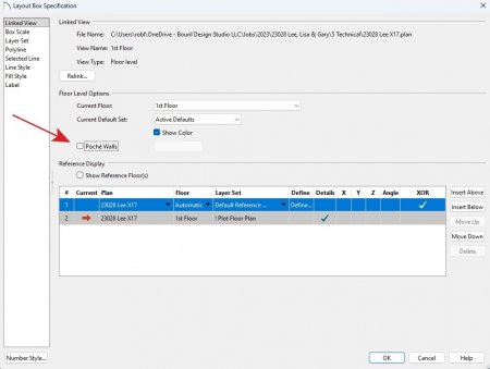
Open the Layout Box object and make sure Poche Walls is unchecked.
-
1
-
1
-
-
20 minutes ago, Renerabbitt said:
is that something other than what I am showing in this screenshot?
I guess it must be my eyes playing tricks, it's just very difficult to tell from the angle. My apologies.
-
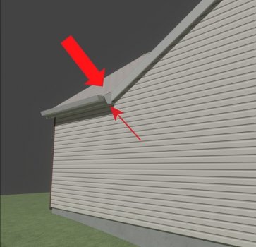
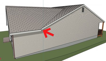
Renerabbit, can you accomplish that while keeping the 12" eave overhang at the intersecting roof plane?
-
I don't think you can get what you want with auto-build turned on because Chief's logic can't resolve the intersection with the garage eave.
-
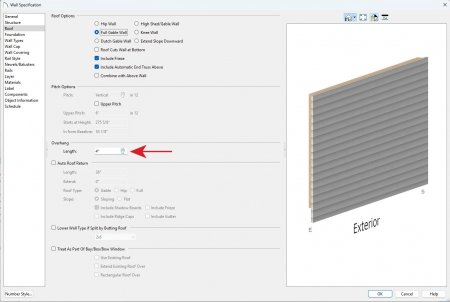
Then select the wall that you want to reduce the overhang, and: Wall Specification>Roof>Overhang>Length
-
Default Settings>Roof>Roof Overhang>Gable
Set the value to what you need, taking into account the thickness of the exterior wall finish.

-
That warning doesn't help you find the specific Layout Box that contains the missing detail that is throwing the error. Remember to turn "on" the Layout Box Borders layer, then page through the Layout to find any "empty" layout boxes.
-
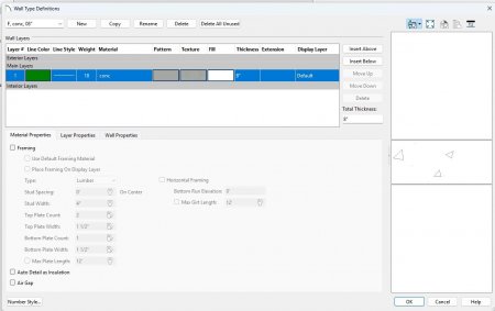
You can accomplish this with pony walls. Define two wall types:
1) the lower wall type will include the framed knee wall; be sure you set the knee wall layer to framing and set up the particulars in the dbx
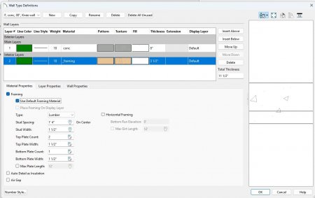
2) the upper wall type is just your basic concrete wall, no knee wall framing
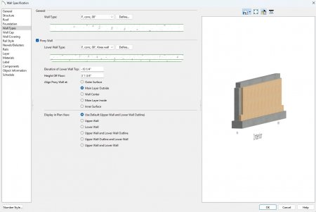
Next, select your foundation walls and turn them into pony walls; set the Elevation of Lower Wall Top to the thickness of your floor framing (I-joist + subfloor), this will build the lower wall type with the knee wall to just beneath the floor framing:
Build Framing and cut a section to see the result. Of course you have to set up your stem wall height, define the foundation walls so the floor hangs off the inside with a ledger, etc.:

This gets you most of the way there. Auto-detailing isn't 100%, it details the knee wall as concrete, but you can easily fix that manually.
-
1
-
-
Here's a link to a Chief tutorial:
-
1
-
-
-
-
Call the JHA or local law enforcement and ask if discharging a firearm within the jurisdiction's limits is permitted; this is always my first step. Second step is to talk cost, ventilation, and lead abatement, as @GeneDavis has pointed out. Third is to ask if they have children living in the house, and inform them of the lead dust residue that will exit the range, clinging to their clothes and shoes.
-
1
-
-
Two suggestions:
1) investigate using a fill pattern (room specification dbx) if the demo area is the entire room
2) if not the entire room, maybe use a material region
-
One possibility is to check the Dimension Defaults for the Default Set you are using:

Another possible solution is to select the Extension - not the horizontal dimension line - and adjust it's length by moving the highlighted grip handle:

-
1. Shoot a Cross-Section view and place an insulation CAD Box:

2. Create a CAD Detail from View. This turns the insulation line into a polyline comprised of arcs and such:

3. This polyline can be easily shaped to fit roof slopes by dragging the center points of the arcs:

-
Here's a library with two versions: full polys (53,987) and reduced polys (21,140). I don't have the hardware to test the light settings, so you'll have to tweak those no doubt.
-
1
-
-
Maybe the OP is referring to the numbers that appear when the dimension line is selected:

-
Step 1: Open Default Settings>Floors and Rooms>Floor Levels>Floor 0
Step 2: Set the Floor 0 Defaults>Structure>Absolute Elevations>Floor value to 0'
Step 3: Set the Floor 0 Defaults>Structure>Relative Heights>Stem Wall value to 4'

Step 4: In Plan View, go to Level 0, select each Room in turn and make sure all the Absolute Elevation and Relative Heights wrenches are checked.

Step 5: Select all the Foundation Walls and ensure that the Wall Specification>Structure>Default Wall Heights>Default Wall Top Height and Default Wall Bottom Height are checked.
Step 6: Go to Level 1 and do the same for all the Exterior Walls, except for the kitchen bump-out.
These steps should take you most of the way there, though you may have to mess around with the kitchen bump-out.

You may also want to investigate this setting for the Foundation Walls: Wall Specification>Structure>Platform Intersections>Ceiling Platform>Hang Floor Platform Above on Wall.
-
1
-
-
If you're referring to using the Wall Specification dbx General>General>Terrain Retaining Wall checkbox, then yes.


Modifying a centerline dimension
in General Q & A
Posted
Select the dimension line and open the Dimension Line Specification dbx. In Extensions/Markers select the appropriate extension (1, 2, etc.), uncheck Default, uncheck Fixed Gap, and enter 0 in Length Away and 0 in Length Towards. Uncheck Marker Style>Mark as Centerline.
Or, even easier, click on the extension you want to modify and manually drag the handles.