

Evolution
-
Posts
971 -
Joined
-
Last visited
Content Type
Profiles
Forums
Gallery
Posts posted by Evolution
-
-
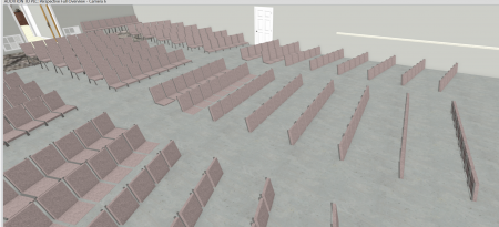
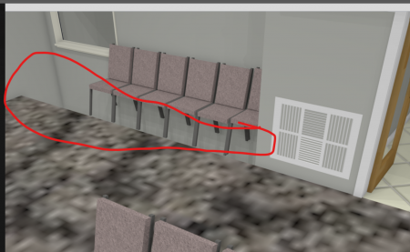
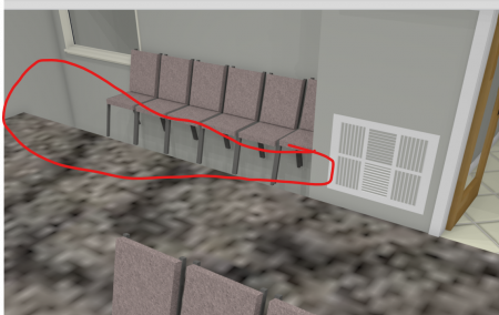
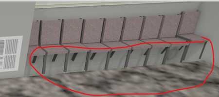
I am still working on the CD's for the Church sanctuary expansion. The problems keep multiplying every time I close and open the plan some strange anomaly jumps up (literally). The structure dimensions have continually changed and I do not have any idea how / why and now in order to get the floor heights to be the same in every room (although) I set them in the defaults, I have to go into each room and now set the floor to zero. I just don't know what to do to keep my drawing from changing constantly. Now the sanctuary floor has eaten my furniture.
-
Well, I took the coward's way out and made polyline solids for each of the spaces missing floor, that quick I solved my own problem.
14 hours ago, Renerabbitt said:is your signature up to date? I might make it more clear that you are on X12 if that's the case
")
Rene, look at my signature "Chief Premier X7 thru X12 with SSA" obviously I didn't renew so I don't have SSA.
Thanks for the help!
-
45 minutes ago, Evolution said:
Rene, I selected the polyline from room (I had already made) converted to a solid. Set the thickness, then selected it and attempted to drag one corner (from a section view of the polyline) down but it doesn't work for me. I watched your video several times (I thought I was doing it the same way) but to no avail.) I may just have to leave it as is and pretend the holes are filled. Every time I make another attempt at it something else goes haywire and causing more grief than it's worth.

Well, I took the coward's way out I guess and created a polyline solid for each hole, change material to the carpet, set the height and solved my own problem. Not the way Rene did it, but I couldn't get your way to work for me Rene.
-
26 minutes ago, Renerabbitt said:
Rene, I selected the polyline from room (I had already made) converted to a solid. Set the thickness, then selected it and attempted to drag one corner (from a section view of the polyline) down but it doesn't work for me. I watched your video several times (I thought I was doing it the same way) but to no avail.) I may just have to leave it as is and pretend the holes are filled. Every time I make another attempt at it something else goes haywire and causing more grief than it's worth.
-
17 minutes ago, Renerabbitt said:
-
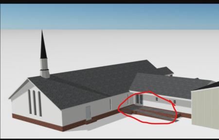
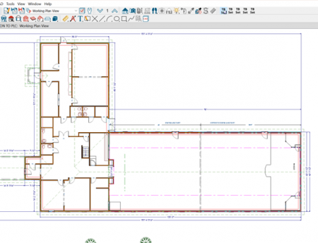
The more I work on this plan the more issues pop up. After finally getting the ramp in place, by first lowering the floor in the existing and expansion floor of the sanctuary I had to stop and fix a dozen different little issues and I don't have a clue what caused them. Now I'm back to working on the sloped floor (using the ramp tool). I have the ramp in place now, but I can't get it to cut into the two areas on each side of the rear wall at the HVAC chases. The break tool and the 3 key, neither one allow me to break the end of the ramp and pull it back into the corners. So I decided to try the create room polyline tool but there is no option to make a ramp out of it. I hate to keep monkeying with the plan as every little change causes the program to go wonkers and delete or change something else.
-
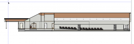
Well, I am still having issues with the sloped floor portion of the existing sanctuary. I kept working on getting the floor lowered in the existing sanctuary and added the ramp and its done; however I can't get the ramp to cut around the two protrusions (which are the return plenums for the HVAC). I attempted to use the break tool and the 3 key method as well but it did not allow me to use a break to pull the ramp around those walls. I believe I was doing it like the training video, so I am not sure why it is not working. Can someone take a look.
The AHJ is going to want to see the sloped floor marry's into the level floor of the expansion floor.
-
8 minutes ago, Doug_N said:
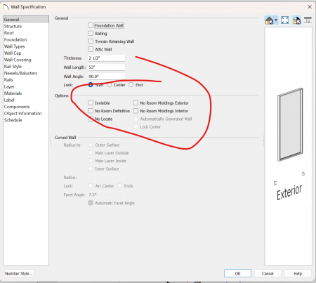
Made one of the walls of a no room definition type.
Doug, that was too simple! I am curious why the other drum pit didn't exhibit the same issue. Those walls aren't selected as "no room definition".
-
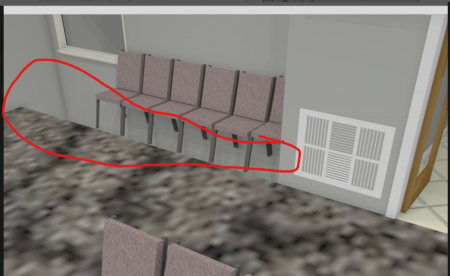
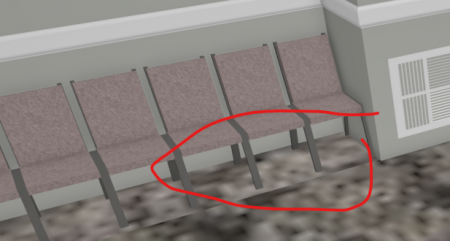
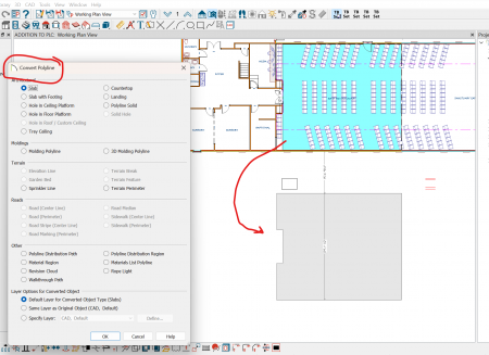
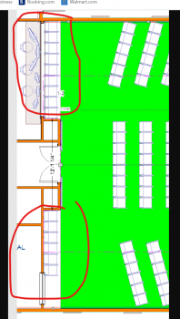
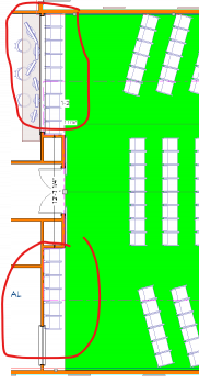
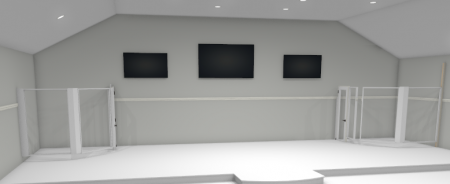
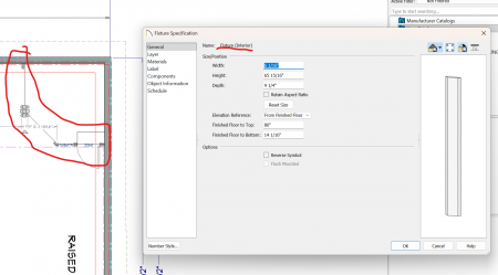
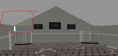
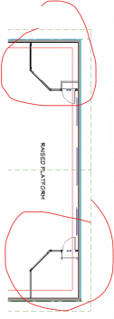
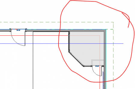
I need to fix the ceiling anomaly that appeared when I attempted to create a room within a room. In order to model the drum pits (there is one on the left and one on the right, I had to use a wall type I created, but after drawing the walls, they would not show in plan view even though I had their layers turned on in my working plan. So finally in order to build the drum pits, I created 3D solids shaped to the angles. it was the only way I could even come close to having the walls show in plan. I assigned room def to each and uncheck roof and ceiling over these two areas. After doing so, the outline of the room (drum pit) on the right side, shows in the ceiling, but not on the left hand side. I'm sure it is something simple, but as usual I'm either trying to hard to find it or not hard enough. In order to get the flooring to show I had to covert the polyline back to a regular polyline and assign "material region" to it to show the flooring as the selected carpet. I have one last thing to try and that is to covert the area I have circled in red to a 3D symbol and add it to the Library.
-
3 hours ago, Chrisb222 said:
Yes. You definitely should start using SPVs, check out the training videos:
https://www.chiefarchitect.com/videos/watch/2421/saved-plan-views.htmlhttps://www.chiefarchitect.com/videos/watch/2433/developing-saved-plan-views.html
https://www.chiefarchitect.com/videos/watch/10199/productivity-tips-saved-plan-views.html
Chris, I've actually watched these videos several times and also the video's related to as-built drawings. I've created several "saved plan views" and within each have attempted turning on and off the particular items I want displayed for each saved plan. That being said, I can't quite get the trick doing the over-lay of the as built to new construction. I'll leave things as they are for now and go back and watch the "Remodeling: How to Generate As-Built Overlays in 2D & 3D - Video | Chief Architect" again.
-
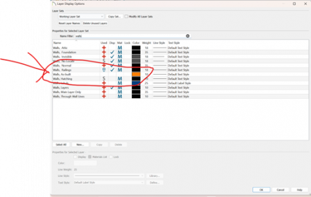
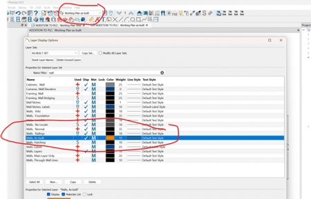
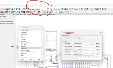
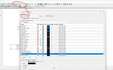
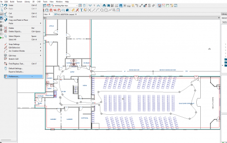
I am working on setting up layer sets (set some up in the edit default tools menu) and noticed that even though I have built a couple of different layer sets, copied from existing sets, with the associated layer's displayed, I want for each, I noticed that there is not an option (at least I haven't found it) to see the new layer available in the layer window (if that makes sense?). You have to select a layer, open, the look for the newly created Layer Set and it's associated layers to display, and I haven't done enough using the different layer options to know how to access them easier. I'm sure the experts on here have it all down to a science but I don't. I'm using CA 12 a lot more now (in semi-retirement) and just getting back up and running, thus the need to have a better workflow. Is that where "saved plan views" comes in? IF so, I'll probably not live long enough to learn to do it that way.

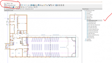
 The layer set I want is not in the project browser either.
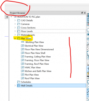
-
19 hours ago, pshelander said:
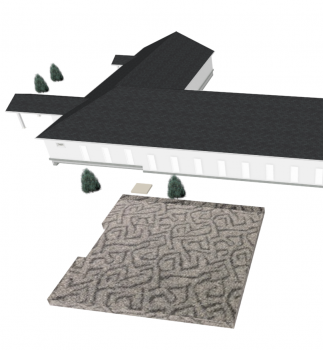
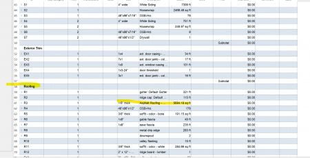
I have been using Chief for many years, but I'm feeling pretty stupid right now. Why won't the shingles that are one of the materials on my roofs show up in the material list? The ridge cap and gutters are listed in linear length. But the actual roofing material is not calculated. My husband is a home builder, and I thought the roofing was listed in the materials list in previous versions of Chief. I'm sure there is a simple answer, but I have spent hours searching "help" and ChiefTalk, and still haven't found the solution.
Make sure in what ever layer you are using you have roof layers turned on.
Thanks,
Pam
-
 1
1
-
-
On 12/16/2025 at 5:19 PM, johnny said:
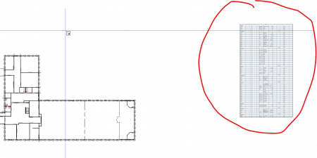
I'm curious if anyone has successfully found a way to publish material list data inside Chief as a schedule?
Johnny, I am using X12 there may be a different option for X16 and newer, but I did this material list from "area" printed as a CA-PDF, save it to file, then imported it into my plan. It can be sent to layout, but if it has to be updated for changes, naturally you have to do a new material list, print to PDF, save to file and import into your plan. Maybe this helps.
-
I have Plan templates for basic project needs, and also layout templates for each discipline. The trick is whatever project you use your templates on must be saved to that Projects File(s). Your Layout template will also contain the project specific information that changes from project to project so each time you use the plan and layout templates for a different project you will save them to that project's folder. It is imperative Plan and Layout files be saved in the specific folder for the specific project. If you change anything from the Plan to Layout they will no longer be linked.
-
1 hour ago, QualicoreHomes said:
To me it looks like some of the foundation walls do not align with your main floor exterior walls.
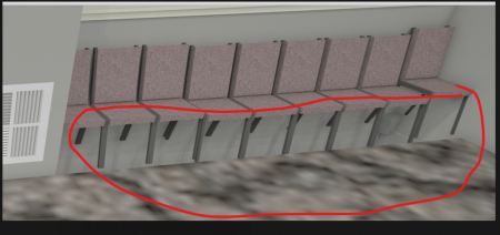
That fixed the gap in the floor. Now to work on the reason the foundation is protruding into the rooms exterior walls, and the gap in the bottom of the exterior wall framing. The issue of the gap in the framing, apparently was caused by my having the wall as a "foundation wall" and the settings in the room DBX calling out the various dim's for the construction of the stem. Setting all the stem heights the same height, (although in the real world they're not the same height) and setting the floor as "Floor under this room" fixed the framing issue. It is a monolithic slab (back filled interior foundation stem walls) but the software doesn't like that apparently thus it stuck the foundation up into the rooms at the exterior walls.
-
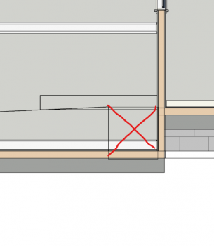
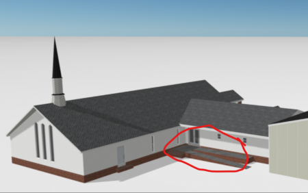
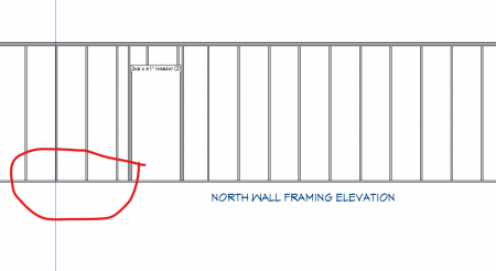
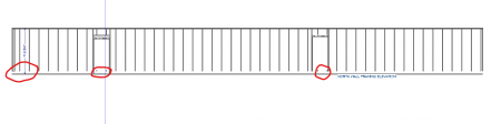
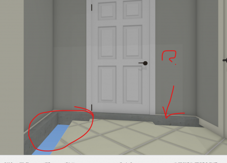
Working on the construction doc's starting wall framing details and the very first wall elevation is definitely not right. I honestly don't know why or at this point what to do. It must have something to do with the way I have the foundation modeled. I have no clue where to go from here?
 Or what needs to change to fix this. The cause may also be the reason there are gaps between the exterior walls in some areas
  as showing in the screen capture the gap on the left is at an exterior wall but the wall at the door is also exterior no gap there but does appear to be part of the stem wall in both cases.
-
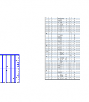
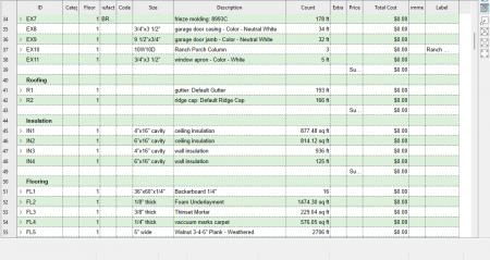
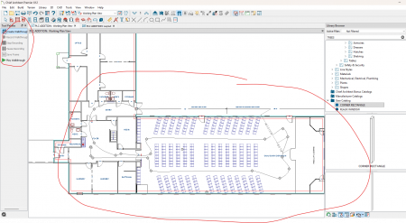
I would like some help from the forum on the best way to build the material list for the expansion only. I attempted the list by "area" and after spending some time on the list it appears to include not only the expansion but the existing for example lighting is for the entire sanctuary. I modeled the plan using a room divider to separate the existing from the expansion and you can select each area independently from one another but that didn't seem to matter to the software when building the material list. My next try was to build the material list by the "room" which obviously only includes the interior finish items and not the Wall, floor construction, Roof or other exterior items. I can't be sure the cut list is correct (it usually isn't). I'm pretty sure building material supplier's will send it back without a bid! Anyone with previous experience with this have suggestions?
-
The building committee chair asked for a material list that could be used to have subs start preliminary pricing. I'm pretty sure I know the answer as to how accurate it may be as well as how to segrigate it to the addition only. Since I've been building for 60 years, I know the process and can advise the chairman the list will not be fully comprihensive and some assumptions will need to be made, such as what to include for demo of parts of the existing building, any temporary roof(ing) etc., potential unknown's such as electrical l/ mechanical oads being added vs existing panel spares vs adding a sub-pnl etc. all of the items that will marry the existing with the expanded sanctuary. I used a room divider to separate the existing from the new construction, and named it the Sanctuary Expansion, I can do a material list for the room (sanctuary expansion) and that should (or at least it appears) to include the exterior finish materials and interior as well. That sound correct?
-
2 hours ago, Mark3D said:
See if that is what you want
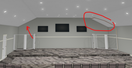
Thanks for the try Mark. The ceiling in the entire Sanctuary is "Cathedrial" the drum pit has a flat ceiling over about 7' AFF of the platform. I built the drum pits with poly line solids since I could NEVER get the walls to show.
-
2 hours ago, Evolution said:
Glynn, I want to do a walk through path not frame by frame because I don't know how to stop the "skaking" results. I tried to understand the instructions in the help file to do the path, however when I attempt it that way it instructs to selecty a codec first then do the path, but if that options is available I don't know where to find it.
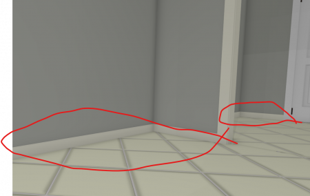
Glynn, as always, you got it! That fixed it. Now I have to figure out why some of my floors are showing a gap between the wall and the floor. It appears to be a foundation intruding into the room. I had set my default for a 32" Stem wall, slab on fill. so I am not sure what's with that but I will do a separate post for that.
-
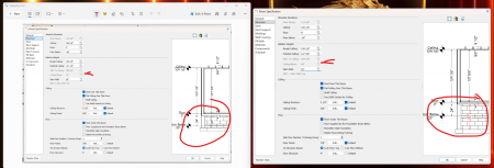
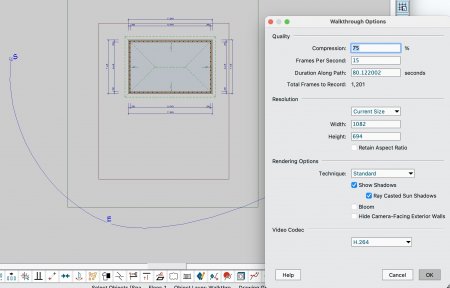
50 minutes ago, glennw said:
I think you have things in the wrong order.
Draw your path.
Select it and then in the edit toolbar select Walkthrough Options - the red circle:
Video Codec is down the bottom.
Glenn, I don't see that option to in the edit tool bar. What am I missing?
Bob
-
44 minutes ago, glennw said:
Do you want to record a walkthrough along a path or do you want to record frame by frame as you move the camera.
If the last, you are on the correct road, when you select save, the view is saved, you can start moving the camera and the video will record.
When you have finished go 3D>Walkthroughs> where you will get some fresh options:
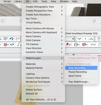
This is from the help file, or do a search for "Recording a Walkthrough" where both "frame by frame" and "along a path" are described:
Glynn, I want to do a walk through path not frame by frame because I don't know how to stop the "skaking" results. I tried to understand the instructions in the help file to do the path, however when I attempt it that way it instructs to selecty a codec first then do the path, but if that options is available I don't know where to find it.
-
53 minutes ago, PitMan71 said:
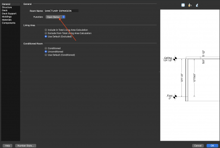
I think this might be due to the fact that the "Santuary Expansion" Room function is set to "Open Below". When I changed that the floor showed up.
hope this helps.
Shane, any idea why the walls are not showing for my drum pit rooms? I'm still battling that issue!
-
1 hour ago, PitMan71 said:
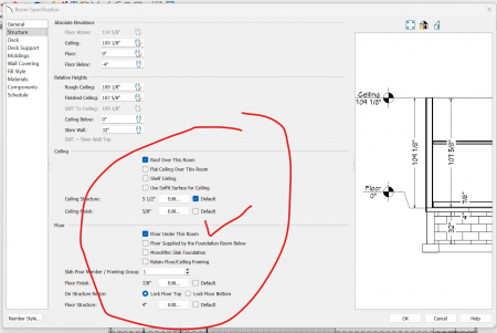
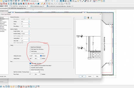
Check the structure panel of both rooms. I think you have "Roof over this room" clicked in only one.
I unchecked roof and ceiling over both to no avail. I get what appears to be a soffit over the drum pit.


 as showing in the screen capture the gap on the left is at an exterior wall but the wall at the door is also exterior no gap there but does appear to be part of the stem wall in both cases.


PRINT PREVIEW SCREWEY
in General Q & A
Posted
Trying to print Permit set for the AHJ (need to have it ready today 3/26/2026) for a 2 1/2 drive to the Building dept office. Have no clue what happened. Here's what the layout looks like.
Then I get this for my print preview...............the steps to the deck suddenly jumped to the next floor up. This hasn't happened before. I didn't change anything on the printer settings. Can anyone help?
COASTAL RESIDENCE FOR CECIL and HELEN WILLIAMS FOR PERMIT.zip