
robdyck
-
Posts
4917 -
Joined
-
Last visited
Content Type
Profiles
Forums
Gallery
Posts posted by robdyck
-
-
16 hours ago, JKEdmo said:
Do you think it's worth a suggestion to Chief to allow these patterns to be automatically available if the materials are already part of the project file
Yes, an 'Add to Library' button would be great, or those patterns in use could just show up in the drop down list.
-
16 hours ago, JKEdmo said:
I learned something today thanks to you.
So did I! I'd never actually done that before.
-
Oh, and don't forget to check the pattern scale...it's 1.5 for your cad polylines. Looks like it works.
-
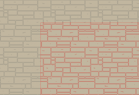
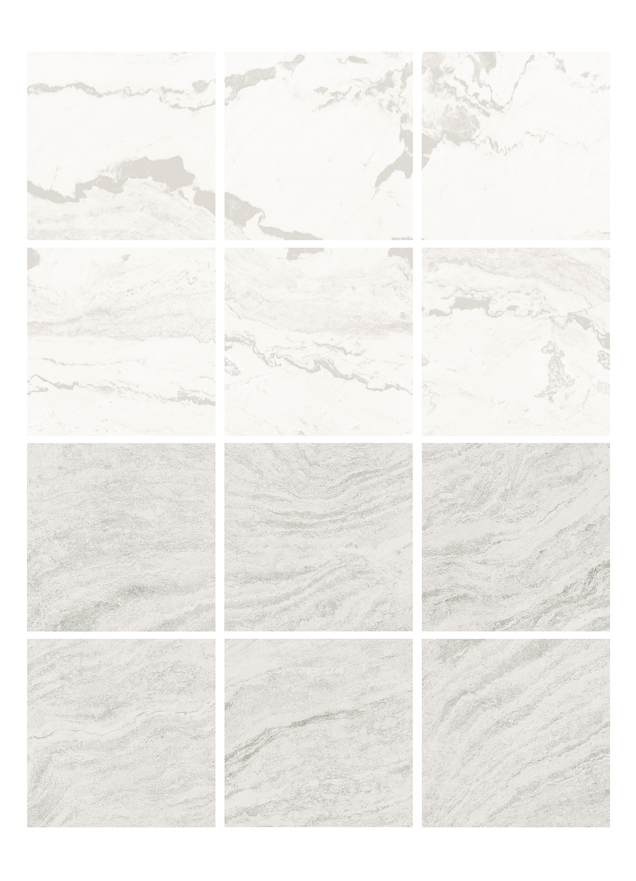
- Add the Material to your library.
- From the library, right click the material and select edit pattern. Marquee select the highlighted area and press ctrl-c.
- Back in plan view, go to CAD>Patterns>Create New Pattern. Name it and make it the same size (32"x32").
- When the window opens, Press ctrl-alt-v (paste-in-place). Close the window and choose Save.
-
 1
1
-
47 minutes ago, capitaldesigns said:
I'm working on plans for a new two story residence. The plans are at the structural engineer office. He has changed the floor joist size from 12" TJI floor joist to 16" TJI floor joists. What the best way to make the change without changing the ceiling height of the second floor ?
Thanks,
Mike
Assuming you make this floor joist depth change correctly, you won't have to worry about ceiling heights as they will move with the floor structure. You WILL need to manually move roof planes up the correct amount and this can be done in seconds by using the transform / replicate tool and moving them 4" up in the z-axis.
-
You could use a separate ceiling plane just for the tile finish or use a 3d solid.
-
And what's up with the constant re-appearance of point markers in a CAD detail?!
-
Yes. I think this is related to the 3d text feature. I have text and text notes in all my elevation views in my template plan. When I open those views and then edit a text box, the leader line jumps, almost as though it is confused about which part of it is a tail or head. For this reason I make sure all arrows never connect to anything...ok not never but usually.
Similar but different...you can't trust a dimension to a roof plane to be there for you later on. It seems that sooner or later, Chief rebuilds the roof and some dimensions disappear...and it's not like you get a tap on the shoulder that says, um, er, I threw out some important information, were you still using that? Oh wait, how about a warning that shows you exactly what Chief has deleted through an auto-rebuild function...or whatever it is that causes that to happen?

-
-
You'll be able to pull all the images you need to easily make a seamless texture image from this site. Just browse the images and take what you need.
-
Please post your plan and I'll take a look.
-
I'd suggest getting all the roofs exactly correct before curving that roof plane. Apply the curve only once all the roof planes are correct and all ridges, hips and valleys are connected.
Then, be prepared to apply fascia and shadow boards and other trim pieces manually.
-
 1
1
-
-
-
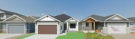
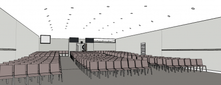
More examples to add fuel to fiery conversation! Awhile back I used google street view to create a backdrop so I could illustrate a home in situ. This process was basic, but it prevented the homeowner from having to make changes to their home because the architectural control board was satisfied with the variation from adjacent homes.
Today, I asked Gemini to improve it.
Here's the original image I created in Chief:
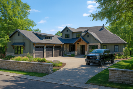
Here's my prompt and the result from Gemini (Nano Banana):
In the attached image, I used a google street view to illustrate my project house ( the white house in the middle) in situ. I'd like you to improve this into a realistic scene by improving the landscaping and lighting. The architecture of all homes in the image cannot be changed.

If you ask me, that's almost unbelievable! That took about 1 minute to prompt and generate. I agree with Chris on this one...if Chief needs to make improvements, they can focus on bringing speed and increased intelligent tools to help with tools related to con docs.
-
1
-
1
-
-
14 minutes ago, DrawingABlank said:
Do you experience the same results?
Nope. I can't replicate that.
-
32 minutes ago, Chrisb222 said:
Do you send it out like that, or keep trying to get AI to fix it?
No, I don't send any AI altered renderings...ever. They can do that themselves, right?
-
I'm not sure Chief really needs a whole lot 'built-in' from a rendering standpoint...not while there are so many other options. D5 has some very interesting features like using AI to build out landscaping using the models and tools. The soft plan examples looked to be pretty heavily modeled prior to rendering enhancements and I find that creating landscapes is quite time consuming. Now, I can send basic renders to any client and they no longer need me to provide great renderings:(.
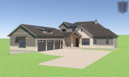
Here's an example that CoPilot generated. My prompts were minimal. I can't do that in Chief in 2 minutes! And yes, it still changed parts of the building.
-
2
-
1
-
-
Are you using Saved Plan Views?
-
You need to divide the foundation into rooms that align with the different floor levels on the main floor. Without this separation, it will continually change. Alternatively, you can delete the foundation entirely...if you have no specific need for it.
The Media Room is marked as Floor supplied...by below. Make this floor structure the same as all other rooms at floor elevation 0".
The easiest way to divide the foundation into rooms is to select the dividing walls from the main floor and the copy-paste-in-place to the foundation level.
The go back to the main floor and check all floor elevations and floor structure conditions.
I have the blue highlighted rooms at 0".
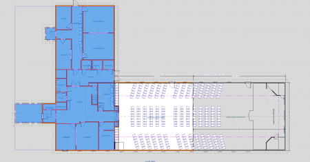
After doing the tasks I mentioned, the result works out as expected.
-
If you can post the plan file or send me a download link, I'll take a look and see if I can help.
-
1
-
-
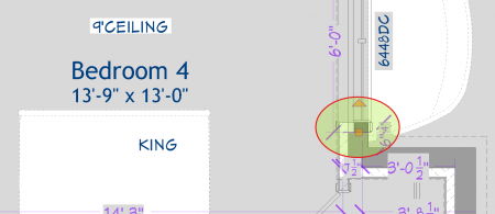
Here's the problem: the small room divider walls that separate the wall types at the window wells. Delete this and it works correctly. Of course, you'll need to figure out another method to control those walls.
-
1
-
-
Here's the problem: the small room divider walls that separate the wall types at the window wells. Delete this and it works correctly. Of course, you'll need to figure out another method to control those walls.
-
-
The gap is the rough opening...because your brick layer is checked as 'framing'. Open the wall definition and make sure that only the framing layers is checked as framing.
-
2
-


Is there a way to turn off or ignore elevation points?
in General Q & A
Posted
You'll need to remove those elevation points. One way to keep track of this would be to place a text marker in the same location, manually enter the information for reference, and then delete the unneeded elevation points.