

jtcapa1
-
Posts
369 -
Joined
-
Last visited
Content Type
Profiles
Forums
Gallery
Posts posted by jtcapa1
-
-
This should have been fixed in the 17.1.2.2 update, if you are still seeing this issue please send in a plan to tech support so we can investigate this issue.
I'll do that. Other than that, I'd say my question was answered successfully! Thanks everyone for all your help.
-
Well I finally found the "SAVE as PDF" in the destination Print dialog box, right at the top. It was fast and worked great! I hate to ask how long that has been there!


Anyway it worked great and the problem is gone! Thanks Doug for the explanation.
Obviously it is a glitch in the 3rd party PDF printer driver software.
-
Guy's,
If he goes to the layers set dialog box can he look to the what's + out in the "Used" column to see what might be affecting it?
I check these when I'm cleaning up a floor plan to save as template
Also, maybe their is something on sheet zero of the layout page
I've got very little in the Layout layer dialog box, I've tried turning the few I had on, off, and turning off those that don't have the red + sign.
-
Well I tried upping the DPI to 1200 and the problem is just as evident for me. Since there is no internal PDF printer like the useful 3d party ones. How do I "save to PDF"?
-
Do you get the same problem using the save as pdf option?
It would be good to have the plan and layout to troubleshoot.
I'll try the internal PDF printer provided by CA and see if it goes away. I'll post my results.
It was on every page of the layout btw.
-
I didn't see it at first either...wouldn't hurt to make notes on the pdf to point it out a little better, but I see it as well. I think this is related to an issue I reported as well and it has to do with using transparent fills.
Basically, if I had any transparent fills, the area around it would 'pixelate' and not stay 'vector'. This would only happen when I would send to 'any' 3rd party pdf printer. It did not happen when I used Chief's built in pdf printer. I reported it to tech support and we did some round and round and I eventually gave up dealing with them because they weren't getting what I was saying or not admitting that they had the problem when I did with each different pdf printer I downloaded and tried out on multiple computers.
If you zoom in really close to where the transition is between darker and lighter, you will notice that the problem part is pixelated, and the good part is not...and it follows a distinct line which I discovered in my testing that it was due to transparency fills and followed exactly the limits of this fill. If i got rid of the transparancy fill, it worked great. You can zoom in on angles, curves etc and you will notice the pixelation...makes for poor printing as well.
so to see if it is the same issue, what pdf printer are you using? is there transparancy fill in your file (either floor plan or layout)?
Drat, I've never looked to see if CA added a good internal pdf printer. I'll have to give that a try.
-
I don't see an issue with your posted PDF so it is kind of hard to comment on what you are seeing.
It is subtle, Like a 25% screen over a portion, if you zoom in 100% you'll see it.
-
Sounds like something that is left over from a previous use of your LO template. If you can select the box and don't feel like it might be anything you need, have you tried just deleting it?
That is my issue, I've not found anything in the template. It seems like there is something there but I cannot find it. It only appears on printing, not on the image on the computer before creating the PDF
-
I've been having an issue with creating PDF's ever since VX7 came out. It is very annoying.
Only way I can describe it is like there is an invisible box over only a portion of the sheet layout and it is causing the layout image on the sheet to look like part of it is being screened. I've searched and searched to see if I've got something on Layer 0, but I cannot find a thing. I've update PDF995 and that did not help. Has anyone else run across this problem??
I've attached a typical D sized sheet showing this anomaly.
-
Larry,
What is it you want to stretch.
There are all sorts of commands that will perform a stretch, depending on what and how you want to stretch things.
I so often need to stretch my entire 3d model, all floors all items in either the X or Y direction. Man I wish there was something like that.
-
Can you explain how that first landing/tread is created with a Volute? You guys tend to skip over the basic key to creating these things.
-
Glenn came up with the cleanest way to do it while we wait for CA to work it into the railing dialog menu.
"This is easy to do with railings.
Build you deck to the correct size and make the railing Invisible.
Draw another rail outside the deck and configure it how you want (no shoe, etc) and make it No Room Def.
In elevation, select the rail and uncheck railing to make it a plain wall (you need to do this because you can't drag the bottom of the wall down if it is a rail).
Drag the bottom of the rail down past the deck.
Make it a rail again.
The beauty of making it from a rail is that it is easy to modify balusters, newels, spacings, heights, handrail, etc."Here is the end result for a recent project of mine:
Last edited by Glenn Woodward; 07-09-2012 at 07:21 AM.
-
Thanks, for the life of me searching I could not find it. Sometimes my search engine skills really suck.
-
I'm pretty slow when it comes to this tweak of the black and white elevation views having heavier line weights as shown by the above people.
So I take a standard "elevation camera view" and I turn on my Layer set and annoset for elevations. In the annoset dialog for layer control
we then turn on just want we want for elevations, but to get the line weights we then adjust things like "roof planes" to a thicker line weight?
but I don't see the layer name for roof hatching to turn that to a grey tone? I do for walls and wall hatching. Although the line weight ends up
light for roof hatching, I'm just not sure how that happened.
I see I've got that wall hatching confused with the plan view interior hatching. So I'm not sure how to set line weights in elevation views. Could
someone do a screen shot of the dialog box to show and example of changing to the roof and walls?
-

I asked this question last year, but cannot find the thread. I managed to get this to work then too! I even have the model still but I cannot do it again on another model.
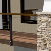
I'm simply trying to get a cable railing to display correctly where the newels are on the outside of the deck edge attached to the rim. This was done by drawing a deck first with an "invisible" deck railing, then draw another rail wall outside the first, and snug it up next to the invisible railing.... BUT.... under the structure tab dialog box the default wall heights dbx is grey out on the one that will not extend below, whereas the one that does extend below the top of the deck, the "default wall bottom height" is unchecked. I don't recall why or how to get that to work.
Any one know???
-
No need for any workarounds or invisible walls.
This can all be done with the Edit Wall Layer Intersections - that's what it's for.
Lew, you need to be aware that even though a post claims to be a bug or workaround, it is not always the case.
Please Glenn, Can you tell me where to find the command "Edit Wall Layer Intersections" I've looked and looked and cannot find any such command in X6.
-
Do you have any error messages you can share with us?
Does it only happen when a 3D view is open or a dialog that shows a 3D view?
It sounds like it could be video drivers. X6 tries to get more out of the video graphics than prior versions so an updated driver may help.
Verify your Radeon is the card being used as well. Open Preferences>Render>Video Card status and make sure it's using the right card and has a relativley new driver.
Thanks for stating this Dan, I've been using X6 on my new laptop for months and I never check which card it was using, then come to find out it is using the built-in slower card. How do you force CA to use the added NVida card instead?
-
Would you guys mind explaining in more detail how you use Annosets to get that look in the elevations? I've tried but seem to have failed. Maybe a screen shot of the layer annoset that produces those fine images.
-
Still it is not parametric or anything, you are forced to use 3d models of various elements and build, set them in place. This is a slow tedious process, but obviously looks great on a 3d model

-
I use a Hexagon for my Window Labels and a Circle for Doors. I know some like to have the size, etc listed directly on the Floor Plan(s) but I prefer having the reference on the Plan and all the rest of the information in the Schedules.
I'm with Joe here. I've tried customizing the labels for each window like (N)3040 X0, but should I change the window, it does not change on the plan. Can get into trouble fast if your not careful. I found the Architect's method of using symbols that refer to a schedule to be much safer in the long run. Plus cleaner. Just not as easy for a contactor to work with.
-
Can you guys that use Layer 0, provide a graphic example of what yours looks like?
I've had some issues with using this method when I send it to a printer, plus what lays over it.
-
AutoCAD has a very easy to use paint tool called "matchprop" that applies the properties of a selected object to other objects clicked upon.
CA has something clunkier, and I was wondering if I've missed something more useful like the ACAD version???
-
There is also a neat trick to get the railing to the outside of the deck so it looks like its mounted correctly using one invisible railing and another visible one just outside that.


Pdf Anomaly
in General Q & A
Posted
Here is the answer from CA's tech support ticket people:
John -
When I follow your instructions, and add the transparency fill to the plan - and then send to layout, I can reproduce it every time. I will forward this issue to our Development Staff; hopefully they can get it fixed.
In the interim, the 'Save as PDF' option will work. Like you, I have been using PDF995 for a long time, so it's critical that we make this and other PDF drivers work. Hopefully, we can get this fixed ASAP.
Thank you-
Nigelk