

DBCooper
-
Posts
2213 -
Joined
Content Type
Profiles
Forums
Gallery
Posts posted by DBCooper
-
-
You can change your window and door label to show the rough opening using the macros I show above. Below, I just added the rough opening size as a new line after the automatic label:
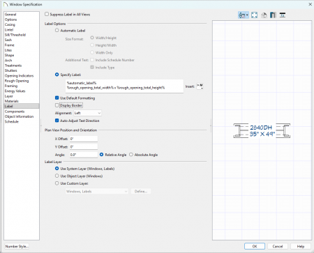
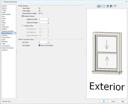
You can change the windows and doors to add whatever you want for the rough opening by telling them to use "additional space". Below, I set it to add 3" to the window width:
-
-
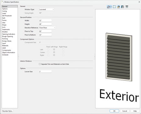
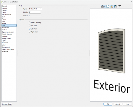
Chief only does exterior shutters out of the box. For any interior shutters, you will probably have to use blinds or just manually place your own symbols. I didn't see any in the library that looked very close though. You might be able to download some symbols from 3D warehouse or even make your own. I played around with making a shutter symbols using a louvered window and that might be a possible solution. You can even make an arched one if you wanted.
-
Copy it to your user library and then you can edit the cad block however you want.
-
I don't know if you can. You can control the layer your dimensions go on through your dimension defaults and you can quickly change these using saved plan views. I don't think you can specify that the auto room and auto exterior go on to different layers though. The best way to do this is to change the current dimension layer, generate your room dimensions, and then change it back to what you want for other dimensions.
Someone else might have some better ideas though.
-
Is your rafter depth is larger than the fascia?
-
 1
1
-
-
All that message means is that the program couldn't make the automatic heights work. Either it did not find the right start or end height, or it is not long enough so that the risers will be too high. You can always turn off the automatic heights and manually set the start and end height to whatever you want them to be.
Stairs need to find a floor platform or landing at both ends in order to make the automatic heights work. If you are using a landing, the stair needs to butt up to the side of the landing for it work. If you are using floor platforms, then the stair would normally butt up against the platform edge at the top but it can sit on top of it at the bottom.
It's hard to tell what the stair is finding just from your pictures. Since it is embedded in the floor platform, it probably isn't going to work like that. You might want to post your plan so someone can poke around in it.
Also, this tech article might help:
-
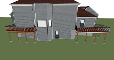
Just picking low hanging fruit. I see lots of plans with framing problems because a wall, floor, or roof layer was marked as framing that shouldn't be or wasn't marked as framing when it should be.
The other common problem with decks is room definition problems. Just make one wall "no room definition" and your framing goes bye-bye.
After that, then you can start looking for all of the other weird cases and that can get very time consuming.
-
 1
1
-
-
See if the pdf matches the screen better if you are in print preview mode. You will need to make sure your page setup also matches what you are using for the pdf. If it does, then you will can probably just adjust your line weights to get the results you want.
If it doesn't, then you might want to try a different pdf driver instead. If all else fails, then you might want to post your plan files or contact tech support.
-
If you are getting weird winders, then you could always just turn them off. It should be pretty easy to manually create those two landings shaped like that picture.
-
Your floor structure is setup wrong. Your joists are not set to be framing.
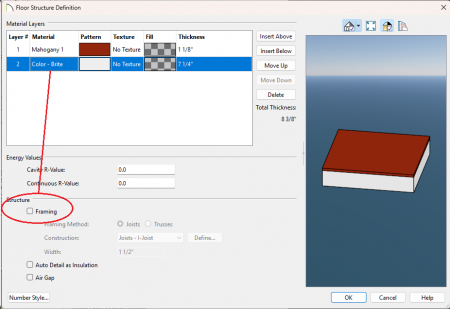
Once you set them to be framing, the decks should look better:
-
1
-
-
Quote
Yes.... Fan/Light combos. So that both switches don't report three way.
Ah yes, that makes perfect sense. Still doesn't explain how they became detached though.
QuoteProjects I started in X15 and then continued in X17 went nuts with electrical. All wiring detached from the switches.
I just checked an old X15 plan I had and I didn't have any problems. It wasn't anything complicated though. If you still have the original X15 plan, you might want to report this to Chief.
-
I think Tyler's post above should be marked as the "solution" since he told you how to fix it. You should be able to change it since you started the thread.
Also, if you are going to update your signature, you might want only one. Right now it looks like you have two signatures, one saying you are using X13 and one saying X17.
-
Something is not working right. Rene is right because it looks like the railing is losing the cad block symbol. It's weird that you only lose it when you draw it with the right-click but not with the left. I would send in a bug report to Chief.
You can probably fix any railings that are messed up by just replacing the newel posts with the good one you have in your library.
-
A very long time ago and in a galaxy far, far away. If I remember right, not having a template was not going to give you any defaults or materials that were any good.
So what did you do to get in this state? You might be able to fix it your preferences or by doing a reinstall from disk.
This tech article might help you:
https://www.chiefarchitect.com/support/article/KB-01866/resetting-template-files.html
-
So some of your switches are set to "auto change" but most look like they are not. Not sure how you got there though. Maybe you set them this way on purpose? Maybe you placed some from the library instead of from the plan defaults? I *think* placing from the library always turns off this option. Maybe you replaced ones in the plan with library ones? I played around with the replace but I got some mixed results so not sure about this one. Regardless, if they are not set to "auto change" then they will not become 3-way or 4-way switches when wiring them.
Also, some of your electrical connections are attached to the electrical objects and some are not. Not sure how you got here as well. The easy way to tell if a connection is attached is to select the connection. If the end handle is a filled circle, then it is attached (to something but it might not always be what you want if you have multiple objects close or overlapping). If the end handle is open, then it is not attached to anything. If your switches are set to "auto change", then they can switch from 3-way, 4-way, or back to 1-way, whenever the connection is made or broken. Not sure if there is something you can do that would cause all the connections to all get lost but it certainly wouldn't surprise me if there was.
None of this actually explains how you got into this state. Hopefully, it will give you some things to watch for to see if you can figure it out. If you do find something, then you should let us know and then maybe report it to Chief too.
-
I think you have some walls set to use the default top and others that are not (probably because you manually changed the height in a camera view at some point). If you pick a wall that is already set to the default top or bottom, then the checkbox will be disabled.
Try clicking on the wall tool and then using "marquee select" to select all of your walls in the plan and then you will be able to set them back to use the default wall top. After that you will need to rebuild all of the framing (not just the walls because you have some floor framing that is sticking out past your walls too).
I'm pretty sure that HD Pro will work the same as Chief in this case but I don't know if your version is old enough that there might be some differences. Probably lots of reasons to upgrade but this might not be one of them.
-
Another way to avoid accidently selecting and moving things is to use layer sets to hide all the things you don't need. Chief's way of using saved plan views is a good way of handling this but I don't know if revit has something similar. If I want to work on the foundation plan, or the framing plan, or the roof plan, or the kitchen plan, or whatever, I can setup my view to only show the things that are important and then hide all the other stuff that gets in the way.
Here is some more info that might help:
https://www.chiefarchitect.com/videos/watch/2421/saved-plan-views.html
https://www.chiefarchitect.com/support/article/KB-03185/understanding-saved-plan-views.html
-
Regarding electrical connections, I spent some time playing with this and couldn't see any problems. I even tried things like turning off snaps to see if that changes things. If you can get this to happen repeatedly, then you should probably report it to Chief. You could also post a plan here to see if someone else has the same issues.
Also, just as an FYI, you can always just turn off the auto switching and then manually place your 3-way and 4-way switches and they won't ever change after that.
-
1
-
-
I think you will get a copy of a material if you have a plan with an old version of the material and then use a newer version from the library. They update the libraries all the time and if they change any setting, then you can get two different materials with the same name. Merging them like Chris suggested is probably the best way to get rid of them.
-
1
-
-
It's very easy with a separate cab.
It *might* be possible with one cabinet, but I'm not sure it's worth the extra work. If anyone knows and easy way, it would be Mark. @MarkMc
-
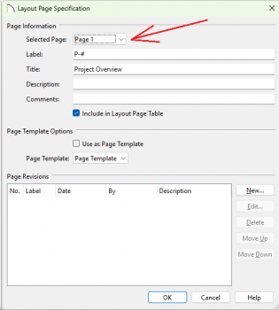
Are you using the drop-down list to change which page you are editing in the layout page dialog? Or, are you closing it and then opening it back up for every page?
-
Like Mark said, you can always turn it off if you prefer to do it the old way:
If you actually want to learn how to use it, maybe start here:
https://www.chiefarchitect.com/videos/watch/10299/x17-file-project-management.html
-
In order to create the drawer box, you probably won't be able to use just one polyline. You could start with one for the outside shape, create another one for the inside shape, and use the subtraction tools to remove the inside area. You will also need a bottom but you may be able to use the inside shape to create that. There are lots of ways to create this box though and this is just one way. Another way that might be good would be to use a molding polyline but you would still need a separate polyline for the bottom.
Once you have the basic drawer box, you will need to convert it into a symbol object so that you can use it in the cabinet.
Here is a tech article that starts with some of the basics:
https://www.chiefarchitect.com/support/article/KB-00761/modeling-custom-3d-objects.html
Here is one that covers converting into a symbol:
https://www.chiefarchitect.com/support/article/KB-00809/converting-an-object-into-a-symbol.html
As for using a custom symbol for a drawer box, this tech article might help:


X17 render crash?
in General Q & A
Posted
This is almost always a video card or driver problem. Sometimes the most up to date driver is the problem.
This tech article has a lot more info:
https://www.chiefarchitect.com/support/article/KB-00106/troubleshooting-3d-camera-view-display-problems-in-chief-architect.html
If all else fails, just call tech support.