

VHampton
-
Posts
690 -
Joined
-
Last visited
Content Type
Profiles
Forums
Gallery
Posts posted by VHampton
-
-
Poly-line solid over the slab is the best way.
Integrate the Chief made slab when drawing the solid for Cross Sectional views.-
 1
1
-
-
On 6/12/2025 at 3:39 PM, Renerabbitt said:
Next tricky part is figuring out how it distinguishes itself with its file name...how the heck do you, the end user, know what the heck is in this backup? Maybe it just asks you to name the backup upon export?
That’s a great question, and a prompt to name the backup at the time of export could go a long way. Even better if it auto-fills with a base name that includes the project title, date, and maybe an optional tag (like “layouts only” or “final set”). This would give users instant context later without needing to open the file just to see what’s inside.
-
Hey Gene,
It really depends on the agreement—and whether interior work is part of it. Sometimes you just have to do what needs to be done, even if it leans more toward interior design than architecture.Chief has the tools to handle just about anything, as shown here. It really comes down to how deep you want to go, and whether the client has paid for and expects that level of service.

-
1
-
-
This looks like a rendering issue in the Layout view, where the arrowhead fill overlaps the callout circle until it's manually refreshed. It's unlikely to be a hardware problem—more likely a display or redraw glitch within Chief.
To minimize the risk before printing:
-
Try toggling zoom levels or pan slightly to force a redraw.
-
Select all callouts on the page and open/close their properties to refresh them.
-
Always use Print Preview as a final check—it tends to show what will actually print.
-
If it persists, report it to Chief Architect support with your image—they may be able to patch it in a future update.
Definitely worth catching before sending jobs to ARCH E.
-
-
You're very welcome Gene.
With the latest releases they now have very good informational videos! -
Yes — Chief Architect X17 does support editing newel placement in railings. In fact, the feature was introduced in version X16 and continues into X17:
-
You can manually move individual newel posts in plan, elevation, or camera views using the Move Newels edit tool, allowing you to reposition them along or offset from the railing
-
You can also add or delete newels with the Add Newel and Delete Newel secondary tools, or restore the default layout using Reset Newels
-
Plus, X17’s feature set highlights include improved control and manual positioning of railing and deck newels
So if you're running X17, just select your railing, click Move Newels, and you'll see edit handles for each newel.
From there, you can drag them to your desired locations. You also have temporary dimension lines to lock in precise spacing if needed.
-
-
On 6/5/2025 at 2:21 PM, Renerabbitt said:
I disagree, updating a template has never been easier. dragging and dropping is a dream. duplicating a complexed linked layout template is super easy. navigating to my projects is faster...like way faster. versioning is faster.
On the flip side, team collab is way more convoluted in project managementinadvertently yes. Huge number of support calls on broken links from people who do not understand where texture files are stored and search for and why renaming a file breaks a linked layout
I see your point, Renne — and you make a good case for the benefits. For someone building out from scratch or looking for a faster way to manage templates and versions, I can see how the new system shines.
That said, I still like my own setup — maybe it’s just old habits. Honestly, this feels a bit like being asked to drive on the left side of the road when you’re so used to the right. We’re still getting to the same destination; it just feels unfamiliar.
-
1
-
 1
1
-
-
On 5/29/2025 at 5:30 PM, DRAWCO said:
This new system is very confusing.
Agree with this observation. Presumably, newer users may or may not have a method for keeping everything in its place, and perhaps they may be the target audience.
There’s definitely a benefit for a team setting — and perhaps that’s where X17 shines. But as for my personal choice, this feels like a feature that’s geared more toward solving workflow chaos than enhancing precision.
If a poll were taken, I’d say the silent majority of experienced solo users won’t be using it. Not because it’s bad — but because it introduces more rules than rewards for those of us who already work cleanly and deliberately.
Sometimes structure is helpful. Other times, it just slows down momentum. This feels like the latter.
-
2
-
-
On 5/28/2025 at 11:40 AM, Steve_Nyhof said:
Please share your thoughts and questions
Subject: Why I’m Opting Out of Chief Architect X17’s File Management System
After spending some time with Chief Architect X17’s new File Management system, I’ve decided to opt out — and I wanted to share why, in case it resonates with others who work solo and value simplicity.
At first glance, the File Management system promises structure and automation. But for those of us who’ve been managing projects effectively on our own — using clear folder hierarchies, consistent naming, and disciplined backups — it adds layers of complexity that don’t feel necessary.
It seems like a solution to a problem I don’t have.
The system introduces rigid folder structures, enforced naming, and automatic file linking, which may be helpful in team environments or for those just starting out. But if you’re already methodical, it begins to feel like Chief Architect is now micromanaging what used to be intuitive.
For example, I already organize my projects by client, keep plan and layout files in clearly marked folders, and archive my own dated versions. I don’t move files once linked, and I’ve never run into a situation where I lost track of a .plan or .layout file. So I asked myself: If it’s not broken, and not in need of fixing — then what’s the point?
Yes, autosave still works as it did in X16. Yes, I can still manually manage backups. And no, I don’t need a system enforcing rules I didn’t ask for, especially when it interferes with the clarity and rhythm of my own workflow.
To be fair, for teams, or newer users, this system may absolutely be worth it. But for seasoned solo professionals, it feels like a layer that solves someone else’s problem — not ours.
Just thought I’d share, in case others are on the fence. If you’ve already got a workflow that keeps you organized and backed up, skipping File Management is not only fine — it might even keep things cleaner.
-
2
-
-
Hi ralt9245,
Don't worry — you can definitely recover your previous defaults in Chief Architect X17.
Here's how to import defaults from an older plan:
Step-by-Step: Restore Defaults from a Previous Plan
-
Open a New Plan (or the plan where you reset the defaults).
-
Go to the "File" menu.
-
Select "Import" > "Defaults".
-
Browse to a plan file (.plan) or layout file (.layout) you created before the reset.
-
Chief will give you options to import different types of defaults (Dimensions, Walls, Roofs, etc.).
-
Select what you want to restore and hit OK.
This will overwrite your current defaults with the ones from the chosen file.
Tip: If you had saved a custom template plan before resetting, that's also a great source to import from.
-
2
-
-
Rob and Renee are absolutely right:
Summary of Steps:
-
Draw a Railing Segment: Create a short segment of your deck railing (e.g., 36" wide) that matches the design of your existing railing.
-
Convert to Symbol: With the railing segment selected, use the “Convert Selected to Symbol” tool. In the dialog box, assign it to the Door category.
-
Save to Library: Save the new door symbol to your library for easy access in future projects.
-
Insert the Gate: Place the custom gate symbol into your deck railing where needed. It will function as a door and visually match your railing.
-
-
Hi there — that definitely sounds frustrating, especially with everything else rendering correctly. Here are a few things to try that often help resolve rendering inconsistencies like you're describing, especially with newer Macs and Chief Architect X16:
1. Check the Material Definition
-
Even if the materials look correct in the plan or library, double-click the fridge and the upper cabinet on the problematic wall.
-
Go to Materials > Diffuse color and texture, and confirm that the correct material and texture are applied.
-
Sometimes a black appearance happens when a texture path is broken or the material doesn’t have a texture map assigned in PBR (Physically Based Rendering) mode.
2. Switch Between Render Techniques
-
Try toggling between Standard, Physically Based, and Vector View in the 3D rendering toolbar.
-
If the problem only occurs in PBR, it's often a material or lighting interaction issue.
3. Check for Overlapping Walls or Geometry
-
Use a top-down view or the "Back Clipped Cross Section" tool to make sure there’s no accidental duplicate wall or object that could be casting unwanted shadows or blocking light.
4. Adjust PBR Material Settings
-
Select the appliance or cabinet, open the Material Definition, and under Properties, check the Roughness and Metallic sliders.
-
If they are maxed or too high, that could make stainless steel appear unnaturally dark depending on the light angle.
5. Light Source Position
-
Add a temporary point light or area light directly above or in front of the fridge and see if that changes the rendering.
-
Also verify the sun angle in the Sunlight Specification dialog isn’t casting shadow directly onto that fourth wall more intensely than the others.
6. Mac M4 Max Optimization
-
If you're using hardware ray tracing, try toggling it off in Preferences > Render Settings and re-render.
-
Also, ensure you're running the latest update/patch for X16, as Chief has been improving M-series support rapidly.
-
-
Correct—if those are 14" roof joists, the sub-fascia needs to account for the soffit as if it's being fastened to the underside of the cantilevered roof framing.
Increasing the sub-fascia depth will eliminate that gap. Chief Architect can handle modern designs quite well, but the framing defaults often behave more like traditional gabled roof setups.
-
Absolutely—rest assured, the folks at Chief Architect do read these forums and take customer feedback seriously. There’s a deep and loyal user base here, and the input shared—especially when constructive—is definitely on their radar.
That said, you're right: posting here alone doesn’t guarantee a feature request is formally logged. Using the beta reporting tool or contacting Chief directly is the best way to make sure suggestions are documented and reviewed. So by all means, keep the discussion going here—but also take that extra step to make your voice officially heard. It makes a difference.
As for me, I’m still respectfully trying to learn more about the upgrades before commenting on features that aren’t immediately apparent. I’d rather understand the improvements fully before weighing in on the new version. -
5 hours ago, Chrisb222 said:
None of that is useful whatsoever for me. Water animation? Seriously?!? Fix the stair tool.
It appears the water tool doesn’t actually animate water—it’s more of a glossy texture overlay.
In effect, it replicates what I’ve been doing for years: using a 1/2" mirror layer beneath a transparent slab with a water texture applied.As for the project management feature, I’m not sure I see the need or benefit. Everyone has their own system for tracking projects, and it’s unclear how this integrates or adds value—at least from a sole practitioner’s perspective.
I could be wrong, but this seems more geared toward multi-person offices where file sharing and coordination are critical. For individuals working independently, it may offer little utility, especially if it's positioned as a key feature in the new version.
-
1
-
1
-
-
The best photorealistic projects still tend to rely on third-party renderers to really shine—but credit where it’s due: X17 brings some great updates. Thanks to the CA team for pushing things forward. The presentations always help sell the project - not just to clients but to the various architectural review boards within each municipality.
Here’s a quick rundown of the new rendering and visualization features, and they're all really helpful:
-
Anisotropic materials – more realistic stainless steel and brushed metal finishes
-
Interactive material mapping – scale, rotate, and adjust textures right in 3D
-
Sun study walkthroughs – simulate daylight changes with a fixed camera
-
Water animation – adds movement to pools, fountains, etc.
-
3D text & dimensions – annotate right in 3D views
-
Cross-section slider – adjust cut planes on the fly
-
Material builder (Windows) – custom tile, wood, and grout control
Still no AI rendering built-in yet, but exporting to Twinmotion, Lumion, Enscape, or D5 is a solid workaround for higher-end visuals.
Looking forward to what’s next.
-
1
-
1
-
-
In reading the initial post, he's trying to place a reverse gable over the front door - by using the dormer tool.
It's not possible... thus the manual roof method. OR the gable roof line tool (see attached video).
Technically they wouldn't necessarily be dormers anyway. Dormers create space within an area where there's need for head room.
That will never be the case on the 1st floor roof. There's no living space.
The reverse gable is a technically an accent, and it needs to be constructed otherwise - meaning not w/ the dormer tools.
This video shows how:
https://www.chiefarchitect.com/videos/watch/1503/using-the-gable-roof-line-tool.html?playlist=95 -
It’s possible the program is struggling because the roof surface over the first floor isn't quite an "attic," which can confuse the dormer tools.
Why not try building it manually? You could copy and paste the (2) roof planes from the attic level, then lower them to align with the roof over the first floor.
From there, manually edit the roof above the first —create the necessary breaks and openings as needed. Presumably the dormer are being shown in the attic level plan.The reverse gable(s) which you're trying to build should be shown on the 2nd floor plan --- so that the roof framing makes sense when that particular plan is being generated.
Anyway... it should go fairly smoothly with a bit of adjustment.
And honestly, getting comfortable with manual roof editing is a great skill to have in Chief.

-
On 5/2/2025 at 7:43 PM, MollyNDG said:
Yes, I do understand how to transfer toolbar configurations, ...but I think the lower section answers my question "Copying Configurations: You can only copy an entire configuration, not individual toolbars."
If anyone knows a work around, I would greatly appreciate it.
Apologies... this is where I was slightly confused by the question... "I want to be able to do this for individual toolbars and have her install these within her pre-made configuration."
As Rene said, there's a way to do this.
Still, there can be many custom toolbars which one can toggle through while working in Chief. It's a reasonable expectation to take the imported one (with whatever unique features) and revert back and forth between this and the "out of the box" toolbars. Over the past 25 years, I've amassed a fairly large collection of them, and can pick and choose between various options when opting to eliminate certain layers... or the appearance of the toolbar itself. Perhaps that's where the disconnect is on my part. The "look" of the toolbars vs. the functionality of the layer settings for a specific tool bar.
On a side, Rene has configurations which are simply beyond impressive. He's posted videos while working with them, and it's pretty incredible. If you've never seen a circular toolbar before, he's got them. Lol
All the best.
-
Yes... there can be many custom toolbars saved in the Toolbar Folder.
While working you can choose to toggle between the various options.
Anyway... this is where they're located (please excuse me for stating the obvious).
In The Chief Architect Premier X16 Data Folder.

Make sure the Toolbar has unique name. Otherwise It could wind up replacing one of the custom tool bars.
The easy way....
- Copy the custom toolbar from the folder location, and paste it into the desktop.
- Rename it (if necessary) - like Molly's Toolbar - and forward it via email or Airdrop.
- The end user can copy and paste into their library Folder. Specifically the Toolbar Folder.
OR... they can use the import toolbar tool and bring it into their system using that method.
More technical answers are below... but the above will work.
To transfer a toolbar in Chief Architect, you can either copy and paste the entire toolbar or its configuration to a new computer or configuration, or use the migration process to import from an older version. You can also reset the migration to re-migrate the toolbar settings.Here's a more detailed breakdown:1. Copying and Pasting:2. Importing Configurations:- Open Customize Toolbars: In Chief Architect, go to Toolbars > Customize Toolbars > Configurations.
- Import Tab: Select the "Import" tab.
- Navigate to the Data Folder: Browse to the folder where you saved the toolbar configuration or the new computer's Data folder.
-
Select and Import: Choose the configuration you want to import and click "Import".
3. Resetting and Re-migrating:- Access Preferences: Go to Preferences (usually found under the File or Edit menu).
- Reset Options: Look for a "Reset" or "Migration" section within the preferences.
- Reset Migration: Choose the option to reset the migration.
- Restart Chief Architect: Close and reopen Chief Architect to trigger the migration process.
-
Choose What to Migrate: During the migration, you'll be prompted to select what you want to migrate from the older version, including toolbars, libraries, and more.
4. Transferring Toolbars Within a Configuration:- Master Configuration: If you have a "Master Toolbar Configuration" with all toolbars, you can make a copy, rename it, and then delete any unwanted toolbars.
- Copying Configurations: You can only copy an entire configuration, not individual toolbars.
-
AI can do some interesting things these days.
Like joining the forum, posting an image, and down the rabbit hole every goes.
The moderators should require legit signatures with versions and operating systems.
@solver would have been all over this one.
-
I could be wrong... The OP wants a gable over the garage which is higher than the gable covering the right side.
On 4/25/2025 at 4:07 PM, Build25 said:I want the house roof line to go into the garage roof line. I know I am missing something simple, but I am unable to find it.

-
Is that a poly-line from a plan view which was made into a CAD detail?
When a poly-line (with solid fill) is converted into a CAD detail, the "fill" can become fragmented.
Blocking a poly-line prior to creating a CAD view can sometimes prevent this triangle effect.
The screenshot of the PDF print looks exactly like this condition.
Is it possible to: a.) send the original plan view to layout?
...or: b.) Make a Cad "block" of the roof poly-lines prior to creating a CAD detail of the view.
Last observation(s)...
Is the PDF being made with the built-in Chief printer? ...or is it a different print source, like Adobe for example?
~~~~~~~~~~~~~~~~~~~~~~~~~~~~~~~~~~~~~~~~~~~~~~~~~~~~~~~~~~~~~~~~~~~~~~~~~~~~~~~~~~~~~~~
EDIT as per Michael's post: This is not an isolated CA anomaly.
It happens with AutoCAD too.
Lowering the dpi quality of the PDF print may help. Allegedly.
Why are There Lines Showing in My Solid Fills?
AutoCAD and most CAD programs approximate solid fill areas by drawing anywhere from two to several hundred triangles to approximate the area. They do this because printer drivers do not recognize filling the complex areas so AutoCAD approximates it based on the triangles that printer drivers will understand. Much like how solid meshes are used to approximate complex 3D objects.And even though the endpoints of the triangles are written identical in the PDF format the rendering engines of PDF Viewers will typically end up showing dashed lines between some of the triangles when they scale the endpoints to the screen which is much lower resolution than the PDF. An 8.5x11.0 PDF at 600 DPI would be 5100x6600 pixels which is considerably higher than today's computer screen resolutions.Below is a sample of standard solid fill output from AutoCAD to most PDF drivers.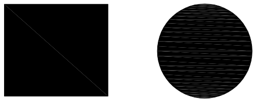 Many PDF Viewers also perform antialiasing on the graphics to make them appear smoother on the screen. If you zoom in on a 1 pixel wide line drawn at 45 degrees it essentially will look like a set of stairs. Antialiasing adds lighter colored pixels around the line to simulate a smoother line to the human eye.Below is a sample of a standard line on the left and an atialiased line on the right.
 The antialiasing is typically what causes the lighter colored lines shown in the solid fill areas from CAD files.
 -
Not sure if your question is regarding a visual for the structure or the finished deck area.
If for the structure... use a grid pattern w/ an offset. Set the size to 48" x 96".
This is typically how roof sheathing (decking) is laid out. In a grid pattern.
If on the other hand this is for illustrating deck boards...
3-1/2" wide hatch can be used or 5/4 x 4 ....or 5-1/2" wide hatch for 5/4 x 6.
Apologies if this response is stating the obvious.
One only needs to make a poly-line in order to create the skin to represent the roof surface.
That poly-line can be given a label which indicates the precise surface area.


-
1
-


X17 Save As PDF Locking up??
in General Q & A
Posted
You're running an RTX 4070 Laptop GPU — more than powerful enough — but Chief may still prioritize CPU or RAM in PDF generation. Make sure:
Dedicated GPU is selected for Chief (not integrated).
Try running in Performance Mode under NVIDIA Control Panel.
Fixes & Workarounds That Helped Others with new versions where the camera dpi is set to 600 by default:
Drop DPI temporarily (e.g., try 300 or 400) to test speed impact — sometimes 600 DPI just chokes the export buffer.
Switch camera views to vector (as you did) or even tech line drawing style to reduce GPU processing demands.
Observations & Potential Causes:
Standard rendering views (especially with shadows, ambient occlusion, or PBR lighting settings) can be memory-intensive during PDF output — even more so at 600 DPI.
X17 may be struggling with raster-to-vector translation or texture memory buffering during PDF compilation.
Since it worked fine in the beta, it's possible something changed in the PDF rendering pipeline in the final build (maybe a bug, or different optimization).