

Chief_Content
-
Posts
503 -
Joined
-
Last visited
Content Type
Profiles
Forums
Gallery
Posts posted by Chief_Content
-
-
We've been working with our brand partner, StarMark, to update their digital catalog.

Downlowd in from the 3D Library, or directly with the Library Browser's tools.
-
2025’s Colors of the Year by brand partners Behr, Benjamin Moore, and Sherwin-Williams are available for download.

-
Find the most recent updates for Legacy Crafted Cabinets on the 3D Library and through your Library Browser's Update tools.

-
Hi All,
Don't panic.
Please refer to this older post and realize these catalogs for purchase are meant for our Home Designer customers only.
The full 3D Plant catalog is still included in your SSA access.
-
 3
3
-
-
Use the Update Library tools or visit the 3D Library to get the latest catalog for Wood-Mode Cabinetry.

Learn more about Wood-Mode products: https://www.wood-mode.com/
-
 1
1
-
-
Get the digital catalog update from Cambria to specify their counters and surfaces in your designs!

Learn more at https://www.cambriausa.com/
Like and Follow to show your appreciation, and stay current on the latest trends.
-
We've worked with our brand partner, Dura Supreme, to update their digital catalog. Use the library browser tools or visit the 3D Library to get the latest version!

Learn more about Dura Supreme: https://www.durasupreme.com/
Like and follow:
-
We've recently updated the digital catalog from our brand partner, Omega.

Make sure you get the latest version using the Update features in the Library Browser, or by downloading directly from the 3D Library.
-
Get the latest digital catalog from our partner brand, Decora.
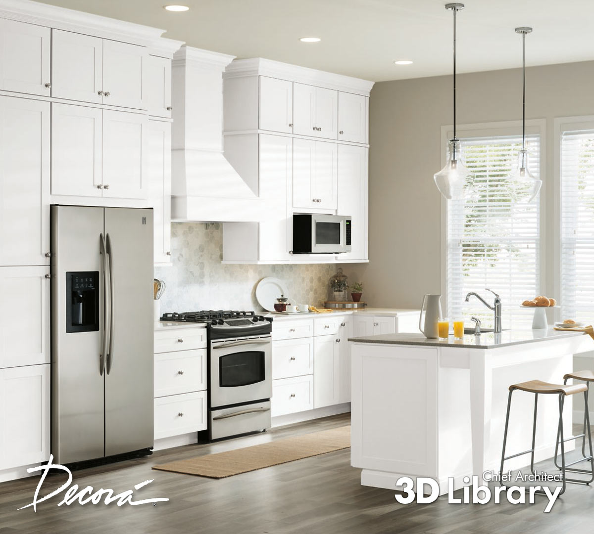
Learn more about Decora Cabinets: https://www.decoracabinets.com/
-
Waypoint's catalog update is ready for you!
Download directly from the Library Browser, or visit the 3D Library.

-
-
Get the latest update from our partner brand, Showplace Cabinetry!

Learn more about Showplace products: https://showplacecabinetry.com/
-
Use these surface mounted electrical boxes and molding profiles to 'run' conduit for utility, commercial, and retrofit needs.

-
-
We've recently updated the Kemper catalog. Use the 3D Library or direct download/update features within the 3D Library to get the latest!

-
Find the latest updates from our partner brand, The Corsi Group via their two product lines Greenfield and Siteline.


-
Find new bonus catalogs available via your Library Browser and the 3D Library.
- Cabinet Hardware No.5 - these are pieces we've pulled from some of the Antiques stylized furniture items. Now you can reuse this hardware and get the look on cabinets, doors, or other custom pieces that you create.

- Lightbulbs No.1 - this catalog was inspired by a user request. They plan to create their own light fixtures using shapes and molding in Chief, then include these lightbulb objects for finishing touches.

-
1
-
Get the newest product information from our catalog partner, Decor.
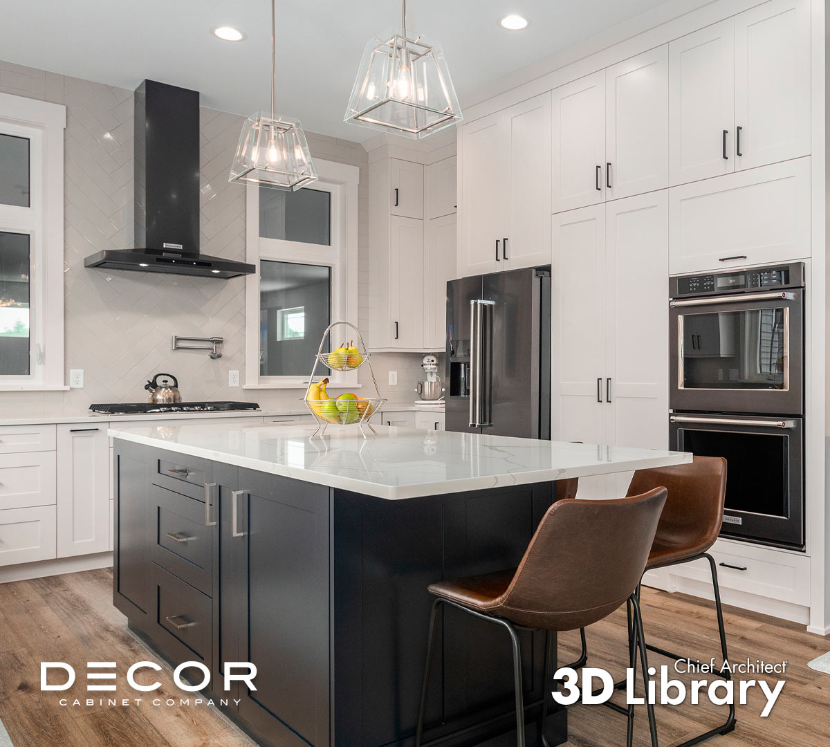
Learn more about Decor and their offerings: https://decorcabinets.com/
Make sure to follow and like to show your appreciation!
-
Get the latest catalog update from partner brand - Homecrest!

Learn more about the available products: https://www.homecrestcabinetry.com/
-
Find the latest product from partner brand, Blum.

Available now on the 3D Library!
Learn more about Blum: https://www.blum.com/us/en/
-
Throw a little shade in your designs with this new selection of window treatments.
Window Treatments No.2 Blinds and Shades

-
1
-
-
Get the latest updates to partner brand, NatureKast's, digital product selection.

Learn more about NatureKast here: https://www.naturekast.com/
Make sure you like and follow to show your appreciation and get inspired!
-
-
We are happy to share our newest brand partner, Kabinart.
Get the catalog from the 3D Library or download directly from within the Library Browser.

Learn more about Kabinart here.
Follow on social media:


X16 Library Browser searching home designer catalogs instead of Chief Architect catalogs
in General Q & A
Posted
Hi @NeidigDesign
It sounds like your log in from Chief is somehow associated with your old Home Designer Account.
This is likely an easy fix - if you can call or reach out to our Customer Service Team, they will be able to look up your account information and make sure that the Chief Architect license with active SSA is the right login for you so that you can access all of the catalogs that are included with your support package.
https://www.chiefarchitect.com/support/#contact
Best,