

Adrean
-
Posts
71 -
Joined
-
Last visited
Content Type
Profiles
Forums
Gallery
Posts posted by Adrean
-
-
18 hours ago, mtldesigns said:
The gap between the trim section and the drywall, is that typical? How do you keep the drywall squared off and smooth like what is shown.. (talking in the real world)?
Yes, the gap is the primary detail, sometimes there is no base at all, just the shadow gap.
Sometimes you'll see tape lighting installed in the recess, which makes a nice ambient lighting effect.
I think there are a variety of channel moulds that are used for installation IRL, as Joe pointed out.
Here's an installation video: https://youtu.be/_Y5ap0u_1lM?si=lZGJQ_xhiIVnLD0N
Sometimes the recess follows stairs, which is also a fun and interesting detail.
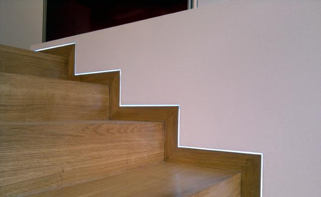
Googling "Recessed Baseboards" seems to return a decent variety of real world examples.
")
Thanks for playing!
Note one clever behavior with this solution: wall material regions recognize door and window openings. This means that the pieces made for the baseboard and recess will dynamically update as your doors are moved. Obviously, those that surround the window and door frame are not connected to the openings and won't move with them.
-
I've been seeing a trim and wall finish detail where base trim is flush to the wall finish and there is a recess at the top and/or bottom of the wall. It is a clean look that I've wanted to render in Chief Architect.
There isn't an explicit feature made to do this automatically, but here is one technique that works pretty well. Can you guess what it is?

Here's the X15 plan if you would like to dissect.Shadow Bead.plan
-
I made this example by taking screen captures of the material texture or color, then pasted as picture over the first cell in each row. I think I had to adjust the draw order for the swatches to show on top.
We've gotten a few requests to do this automatically in Chief, unfortunately, the feature isn't available quite yet.
I've made a note to add your request for our team to review!
-
 1
1
-
-
Thank you @SusanC it was a long project and I lot of work, but I think it is a great resource and improvement!
I'm glad to have been invited to contribute and to represent Chief Architect!
-
1
-
 1
1
-
-
carowe, you may be able to use the screen capture tool that comes with Chief to capture some tile images like your examples.
We cover just this topic in this video:
https://www.chiefarchitect.com/videos/watch/10145/creating-custom-tile-materials.html
-
Doug, what you are seeing in the Weighted Pendant is a known issue with OGL rendering. When there are two surfaces that have transparency values overlapping in an OGL view (like standard or PBR), the engine doesn't know which surface to draw first, and sometimes draws the surface in the background on top of the foreground surface. I believe if you were to ray trace these tests, the affect would be much diminished.
As mentioned before, there appears to be a surface issue in the Arts & Crafts Pendant that we've charted for updating.
Regarding the Surface Mount Tube light, we received the plan, and can see some Z-fighting happening as some of you have described. I am unable to reproduce with a new plan, so I've submitted the example you've shared to our development team for review. Thanks for sharing your experiences with us!
-
Very strange behavior indeed!
I would not think that the behavior of the surfaces on these light fixtures would be dictated by a Template unless it is a default material issue. AFAIK the templates we distribute haven't referenced these tube lighting symbols; though a custom template that contains older copies of these objects could be a culprit. We did recently rename these items to use the word "Tube" instead of "Fluorescent" in X10 catalogs. You could open the specification of the object to see if the item has the old name. You could also use the "Replace From Library" tool on the offending objects to ensure that you are leveraging the most current version of the symbol (assuming your catalogs are up to date).
If you've done all of these things and are still seeing the missing surface behavior, please submit a support ticket so we can understand and track the issue in its entirety. Feel free to share this thread's link with our support team, and I will lend what I know about it to trouble-shoot so we can get to the bottom of the problem.
I'll make a note of the lighting properties that need to be improved for these objects and tackle those (I'm a little surprised that these objects are being used at all, TBH, I would have suspected we were specifying recessed cans much more frequently).
Thanks for your efforts working on identifying the problem!
-
1
-
-
Thanks for tagging me, Mick!
I'll log the Arts & Crafts Chandelier issue and we can get it tackled in an update. I cannot reproduce missing surfaces on the Flush Mount Tube lighting. I suspect this could be related to the "Clip Surfaces Within" setting, but to be sure, please create a support ticket that includes a plan containing the offending object.
Regarding the Wayfair Catalog, we did import their 3D ready objects to convert them into a Chief Architect format, I can report this object quality issue to their team and work with them on an update for objects like these.
Best,
-
On 10/15/2018 at 6:31 PM, Kbird1 said:
Adrean on the Content Team will need to fix the default fireplace I guess , maybe more have this issue or we are "seeing " it all wrong???
Unfortunately, because these fireplaces are parametrically generated (like windows and doors) their surfaces are hard-coded, and not something our content team can impact. Updates to the fireplace tool would have to be made progamatically and released in a new version.
If you'd like to see changes to these tools, you can send us reports via the Suggestions Thread or our suggestions e-mail and we will be sure to document them for consideration!
-
Love to see all of these beautiful scenes!
Don't forget to post some of these images in the Gallery Section as well.
We've been featuring this sort of work on our social feeds using #ChiefSpotlight.
You can also follows on Facebook and Instagram.
-
True! Good tip!
One thing I like about the elevation option is that I can add a polyline label and dimensions. The disadvantage is that it is more steps and isn't dynamic if your plan changes.
-
Maybe not incredibly practical or useful, but after wanting to visualize the potential sheet layout for subfloor per platform, I threw together this little hack.
1. Create a CAD Polyline that represents the floor platform for each level (there are a number of ways to generate the polyline, I went old-school and used a CAD Rectangular Polyline, then added breaks to snap it to the corners of the platform).
2. Create a new Elevation view that faces the top of your screen, make it outside of the boundaries of your model, so you don't intersect the existing structure.
3. Copy/Paste the CAD Polylines into the elevation view.
4. Convert the polylines to a solid, then apply a material that is set up with the "Brick" pattern, scaled to your sheet size.
Now you you have a little sheet layout. You could use this visualize how much waste you might have at the corners of your platform, or for a variety of other things.

I saved my camera, and moved it and the Solids to a new layer "Subfloor Diagram" that only displays in a new Layer Set that I created for this use.
-
Ha! Thanks! I'm still super-curious to see / know what other people would do with a lot like this... been feeling like I'm talking to myself out here.
These were some of my criticisms of the designs that have been shared so far:
Re: Prairie
- What's with the smaller garage bay? Is that even a possibility?
- All those corner windows will be expensive.
- Why cram the dining set all the way in the corner farthest from the kitchen? Sure it is just furniture, but what are you thinking?
- The Master Closet could be 2' deeper without affecting the Master Bedroom's usable size. A closet that small wouldn't fly in MY area at this price-point.
- You get into the Master through the Office?! Not sure it that is the silliest idea I've seen or pure genius.
- The upstairs layout is very clean, not sure about that screen porch. Is that excessively whimsical? Are screen porches even a thing in Idaho?
- I like the exterior style, the hill does get in the way for the rear arrangement.
- I'd live there (if I had 2.5 kids).
Re: Contemporary
- The first floor feels like a small space for a "Public" area. How will dinner parties feel? Does everyone have to tromp upstairs for cocktail parties?
- There is no entry closet. A coat rack might not be enough.
- A high-end kitchen built under the stairs? This isn't Europe.
- The Master access to the patio is nice, but it is right at the front of the house. Who will really be using it?
- Calling your "Closet" a "Private Hall" might be a cop out.
- If you have teen-aged kids, they are going to be sneaking out all the time from that big deck.
- This house might be noisy with the open space between all the floors.
- Is that top floor a waste of space, time, money...
- ICFs all the way up? Maybe for the main floor only, Crazy.
- Detached MIL quarters? You are my hero.
- I like the way the exterior is divided into multiple "Styles" to break up the design.
- Cool exposed beams, especially in the top floor... hello 'zen'.
Re: Traditional
- This house looks a bit boring from the outside for its size.
- What is with all the angles?
- Some of those rooms are weird shapes. What are you going to put in them?
- Guest room doesn't have a closet.
- That guest bathroom IS a "Hot Mess".
- Is 1 bathroom upstairs enough?
- Are people going to want a house with "Unfinished" space?
-
Here's another one I like to call "Hot Mess".
It is an attempt and Traditional-Contemporary, split level, w/ angles... trying to keep a shallow slope driveway and point the house toward the views.
- ~3050 sq. ft.
- 5 Bed
- 3.5 Bath
- Unfinished Bonus Room over Garage
What do you think?


-
2
-
I was thinking about Martin's post on the facebook feed last night, and burned a few hours of TV time Chiefing instead.
Here is my interpretation of a passive / efficient house w/ a smaller footprint that potentially takes out just one tree.- ~3300 sq ft
- 3 Levels
- 4 Beds
- 2.5 Bath
- Bonus/Loft Space
- Detached Studio / MIL Quarters
Some things I tried to incorporate:
- SIP Roof Panels
- ICF Walls
- Rainwater Collection
- Open-air space in the "Hot" area of the house with openable windows to encourage the stack effect.
- Sun Studies for June 21 and Dec 21 to see how much sun gets inside
- Daylight Basement for natural insulation
- I intended to add some Thermal Masses to the front interior, via flooring material, but didn't get that far.
Edit: I updated the plan by widening the center section by 2'. This made more room for Kitchen and Powder, and gave a better traffic flow to the Living and Family rooms. Increased living space by ~250. Updated plan attached.


-
Here is an idea I was playing with on the lot...
~3300 sq.ft.
5 Bed
3.5 Bath
It is a variation on the Prairie Style... I don't think this style would really work in the neighborhood or for a hill like this, maybe better suited to a flatter location, but it was fun to come up with a floor plan to sit in the space and try to take some advantage of the views.
There are some possibly 'off' elements in the floor layout... I'm curious to see if others think the same.
I didn't take into consideration any structural requirements...
I'm really interested in seeing what other people come up with!


-
FLOR (a carpet tile company) has this online layout tool for their products.
http://www.flor.com/design-studio/
Once you come up with a pattern for a carpet design, or a full area rug design, you can take a screen capture and import it into Chief as a custom material. Set repeating patterns with texture scaling so it will fill a floor, or set area rug designs as "stretch to fit" then create a Material Region or Polyline Solid the dimensions of the rug to paint the material onto.
Could be a fun way to get clients involved in part of the design process.
-
1
-
3
-
-
Chopsaw, I'll see if I can come up with something to share.
In essence, my approach would be to take a screen capture of the map and/or satellite view from website, and import that into chief as a picture, scaling it and aligning it to the terrain perimeter.
Next, I would find the elevation 'points' on the website's map for each corner of the lot and any other landmarks, then create correlating elevation points on the picture imported into Chief.
Once you have some good anchor points, you can start bisecting them to find the midpoints, on and on until you have enough elevation points in Chief to show a reasonable topo.
The example I was using was a sloped lakeside lot. The site's elevation data didn't appear to account for the existing excavation and pad flattening that has been done on the site, so for that scenario one would have to infer the elevations of flattened regions and roads and change the Chief topo accordingly after they've established a base. It did seem to give me a reasonable natural slope, though.
Best,
-
Attempting to put together a plot plan with terrain elevation this weekend, I came across this site that I thought was handy.
https://www.daftlogic.com/sandbox-google-maps-find-altitude.htm
It isn't an elegant site, but you can enter the address for the property that you are working on and simply click the image to find the elevation for that "point". I was able to put together a reasonable terrain in Chief quickly using this tool.
Certainly not great for a final project, but a good start for the conceptualization phase.
-
3
-
-
Hi Todd,
The catalogs on the 3D Library are not Operating System specific, only The Product (Chief Architect, Home Designer, etc), whether you are logged in to your SSA account, and the Version you are using on each system should affect your access to catalogs. If you are seeing differences, there is either an unintended flaw in the design, or some other issue that we have not experienced in our testing.
It would be very helpful for us if you could contact our support team and give them some specific information about the differences you are seeing. Once we understand what is going on, we will be able to do a better job clearing this up for you.
Best,
-
Here's a fun one for Tiles, and you can screen capture the images to use for textures:
-
1
-
-
Thanks for the suggestion!
I'm looking at recording this one and linking it to older requests as well.
Do you have a term or name for this style? I feel as though I've heard it called a few different things in the past, each of which have slipped my mind at the moment.
Please share the names you know this sort of soffit transition to be called and I will make certain it is documented.
Thanks!
-
Here's a tip that might be relevant to this thread... maybe you all know about it, but I stumbled across it recently.
You can obviously click on any of the gallery images to see them at a larger scale, but this view is limited to your browser window size.
Did you know that you can right-click on that image, and choose "Open image in new tab", to access a full scale version of the image and see it as the poster intended?
In the new tab, you may even be able to zoom in a little closer for more detail. The cursor should indicate if it is full zoom or not.
This functionality might be browser specific... I use Chrome.

-
I am looking at these two images and wondering if it is really worth it for a quick ray trace vs. just using the standard view with shadows.
https://chieftalk.chiefarchitect.com/index.php?/gallery/album/20-comparing-renders/
The Ray Trace only cooked for about 6 passes in 3 minutes. Fairly small size image.
Wow, they are definitely similar! The ray trace is visibly "softer" looking, but if you are providing the images in a relatively small resolution, maybe the final view render works in this case.
Interesting test, thanks for sharing!


Shadow Bead / Floating Drywall Technique
in Tips & Techniques
Posted
Thanks for re-posting your video, @Renerabbitt.
Looks like I should have scrolled my search results a little more before I shared my version!
Here's the original Q&A post for those who want to see prior discussions: